A coil turning frame with a positioning control device

A positioning control and stand-up technology, which is applied in the manufacture of inductors/transformers/magnets, electrical components, circuits, etc., can solve problems such as coil dumping, and achieve the effect of turning over smoothly

Active Publication Date: 2017-12-26
CHINA XD ELECTRIC CO LTD
View PDF10 Cites 0 Cited by
  • Summary
  • Abstract
  • Description
  • Claims
  • Application Information

AI Technical Summary

Problems solved by technology

At present, the coil turning frame used by various manufacturers has a relatively simple structure. Only one side of the coil is protected by a sponge, and the other side is protected by a tightening belt. The electric or hydraulic mechanism is used to turn over. There is a risk of the coil toppling during the turning process.

Method used


Image

  • A coil turning frame with a positioning control device
  • A coil turning frame with a positioning control device
  • A coil turning frame with a positioning control device

Examples


Embodiment Construction

[0027] The present invention will be further described in detail below in conjunction with the accompanying drawings, which are explanations rather than limitations of the present invention.

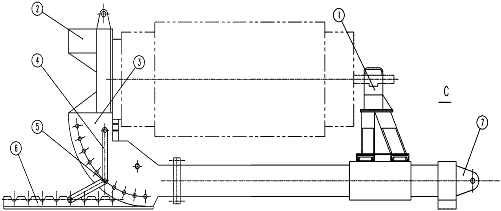
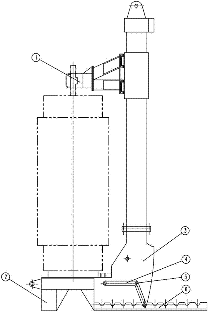
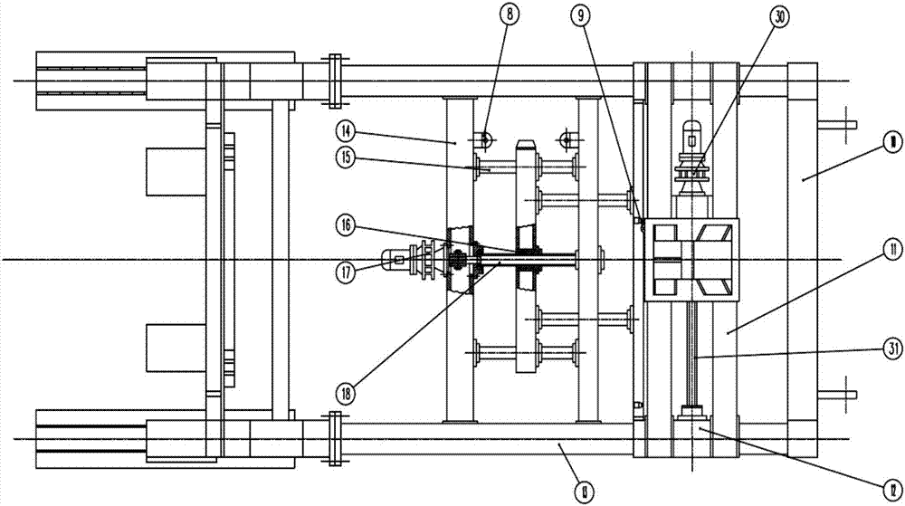
[0028] Such as Figure 1 to Figure 5 As shown, a coil turning stand with a positioning control device of the present invention includes a movable support seat 1, a foot pad 2, a turning mechanism 3, a support foot 4, a shaft circlip 5, a seat 6, a hanging climber 7, and a travel switch 8. Iron stopper 9, connecting beam 10, lateral guide rail 11, first slider 12, upward guide rail 13, beam 14, light rod 15, copper sleeve 16, first cycloid reducer 17, first wire Bar 18, ring 19, first parallel iron 20, second parallel iron 21, handle 22, semicircular ring 23, latch 24, screw rod 25, nut 26, cotter pin 27, cover 28, second slide block 29, the first Two cycloid reducers 30 and a second lead screw 31. The two semi-circular rings 23 on the movable support base 1 are detachably connected thr...


PUM


Abstract

The invention discloses a coil turning stand with a positioning control device, which comprises a turning mechanism, a hanging climber arranged at one end of the turning mechanism, a step, a foot and a seat at the other end, and when the turning mechanism is in a horizontal state, through positioning The control device is set on the movable supporting seat on the turning mechanism, and the movable supporting seat can move forward, backward, left, and right relative to the turning mechanism; when in use, the lying coil is placed on the turning mechanism, and the end of the lying winding coil with a thimble is fixed on a movable On the moving support base, the other end is fixed on the feet. After the coil is installed, use the crane to lift and climb, turn the stand platform from the horizontal state to the vertical state, and use the support feet to connect and fix the turning mechanism and the seat. The seat is connected to the ground. The anchor bolts are used to fix it firmly, so as to ensure the stability of the turning mechanism, and the coil can also remain vertical without being affected, and the coil changes from horizontal to vertical, so that the subsequent process can be carried out.

Description

Technical field: [0001] The invention relates to a coil turning stand with a positioning control device, which is used for turning a horizontally wound coil into a vertical state to facilitate subsequent processes such as demoulding. Background technique: [0002] The transformer coil winding equipment is divided into a horizontal winding machine and a vertical winding machine, and the demoulding operation is performed after the coil winding is completed. When taking the horizontal winding method, after the coil winding is completed, the coil needs to be turned from the horizontal direction to the vertical direction, so that the demoulding operation can be carried out smoothly. At present, the coil turning frame used by various manufacturers has a relatively simple structure. Only one side of the coil is protected by a sponge, and the other side is protected by a tightening belt. Electric or hydraulic mechanisms are used to turn over. There is a risk of the coil toppling dur...

Claims


Application Information

Patent Timeline
Patent Type & Authority Patents(China)
IPC IPC(8): H01F41/092
Inventor 陈婕徐一王春艳朱燕顾永培
Owner CHINA XD ELECTRIC CO LTD
Why Eureka
Try Eureka