
Ultrasonic scalpel excitation device and excitation method
An excitation device and ultrasonic scalpel technology, applied in medical science, surgery, etc., can solve the problems of high electrical signal transmission accuracy, large space occupation of circuit boards, and small component performance drift, achieving high electrical signal transmission accuracy and occupying circuits. Small board space, good effect on cutting human tissue
- Summary
- Abstract
- Description
- Claims
- Application Information
AI Technical Summary
Problems solved by technology
Method used
Image

Examples
Embodiment 1
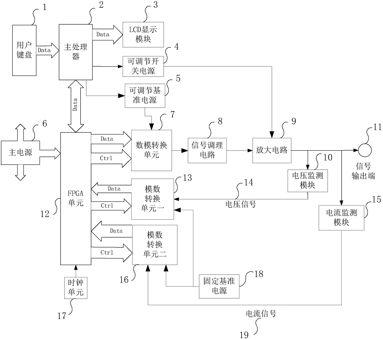
[0041] Such as figure 1 Shown is an embodiment of the present invention, a kind of ultrasonic scalpel excitation device, comprises main processor 2, main power supply 6, fixed reference power supply 18, user keyboard 1, LCD display module 3, FPGA unit 17, digital-to-analog conversion Unit 7, A / D conversion unit 13, A / D conversion unit 2 16, adjustable switching power supply 4, adjustable reference power supply 5, clock unit 17, amplifier circuit 9, signal conditioning circuit 8, voltage monitoring module 10, current monitoring module 15. Signal output terminal 11.
[0042] The main processor 2 is connected with the user keyboard 1, the main processor 2 is connected with the input end of the LCD display module 3, and the LCD display module 3 displays the running status information, gear setting information, and error alarm information of the host device, and the main processor 2 It is connected with the adjustable switching power supply 4, the main processor 3 is connected wit...
Embodiment 2
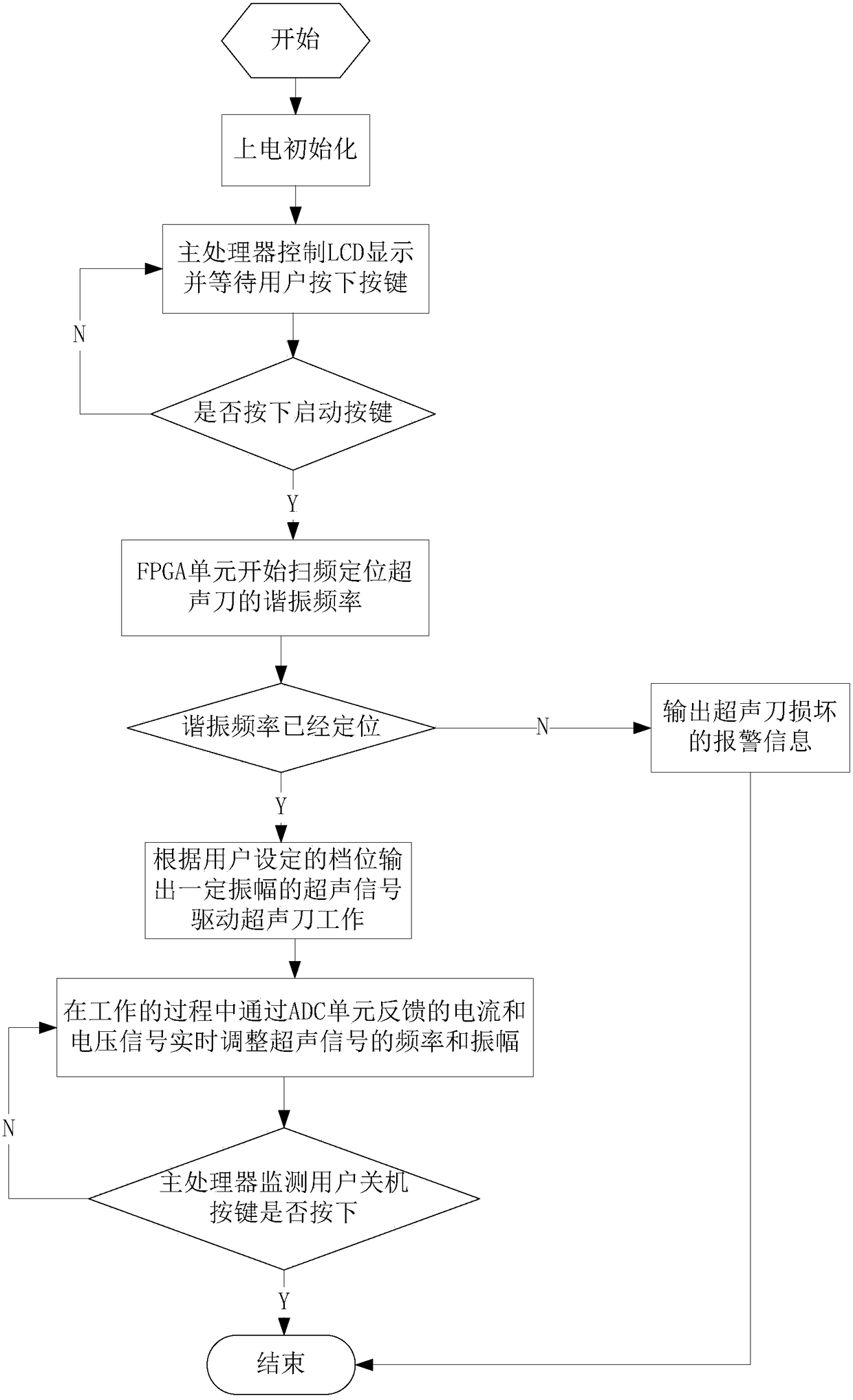
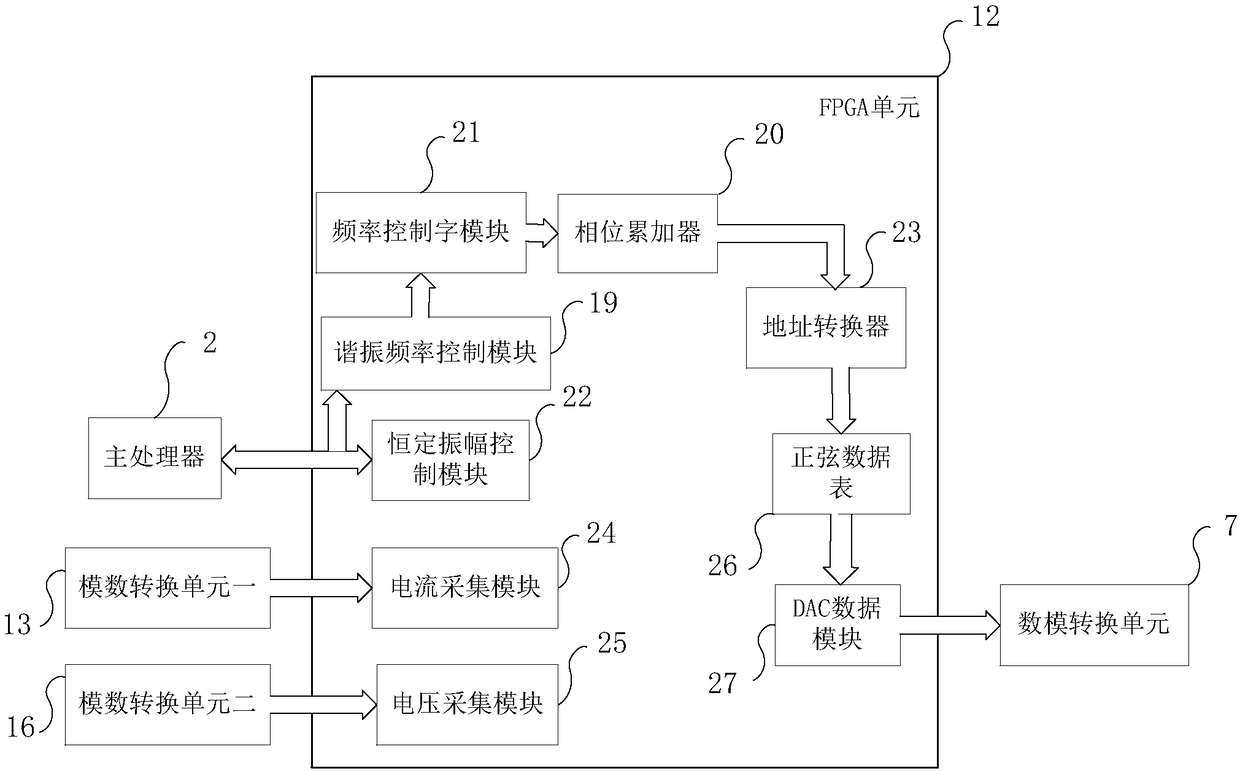
[0056] Such as figure 1 , figure 2 , image 3 Shown is a schematic diagram of another embodiment of the ultrasonic scalpel excitation device of the present invention, and this embodiment mainly further defines the structure and function of the FPGA unit in Embodiment 1, wherein image 3 It is a structural block diagram of the FPGA unit. As can be seen in the figure, the FPGA unit 12 is internally provided with a resonant frequency control module 19, a phase accumulator 20, an address converter 23, a sine data table 26, a DAC data module 27, and a frequency control word module 21 , constant amplitude control module 22, current acquisition module 24, voltage acquisition module 25;
[0057] The resonant frequency control module 19 is connected with the main processor module 2 and the frequency control word module 21 respectively, the frequency control word module 21 is connected with the input end of the phase accumulator 20, the output end of the phase accumulator 20 is conne...
Embodiment 3
[0076] Such as figure 1 , figure 2 , image 3 , Figure 4 Shown is another embodiment of the ultrasonic scalpel excitation device of the present invention, wherein Figure 4 The structural block diagram of the main processor, as can be seen in the figure, the main processor 2 is internally provided with a PWM generation module 28, a keyboard data receiving module 29, an LCD display control module 30, an FPGA data interaction module 31, and a reference power supply adjustment module 32; The PWM generating module 28 is connected with the adjustable switching power supply 4, the keyboard data receiving module 29 is connected with the user keyboard 1, the LCD display control module 30 is connected with the LCD display module 3, the FPGA data interaction module 31 is connected with the FPGA unit 12, and the reference power regulation module 32 is connected with the adjustable reference power supply 5 .
[0077] Among them, the adjustable switching power supply 4 refers to the ...
PUM
 Abstract
Description
Claims
Application Information