Castor with damping function

A technology of casters and functions, applied in the directions of casters, wheels, transportation and packaging, can solve the problems of equipment damage, casters have no shock absorption function, unfavorable equipment protection, etc., and achieve the effect of simple structure and safety guarantee.

Pending Publication Date: 2016-09-21
CHENGDU DIANSHI CREATIVE TECH
View PDF0 Cites 17 Cited by
  • Summary
  • Abstract
  • Description
  • Claims
  • Application Information

AI Technical Summary

Problems solved by technology

With the continuous development of modern technology, more and more different casters are used for various equipment. Ordinary casters do not have the function of shock absorption. When the equipment moves on uneven ground, it is easy to cause damage to the equipment, which is not conducive to protection of equipment

Method used


Image

  • Castor with damping function
  • Castor with damping function
  • Castor with damping function

Examples


Embodiment 1

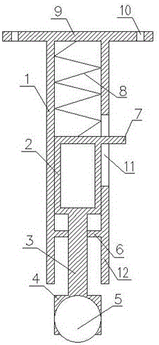
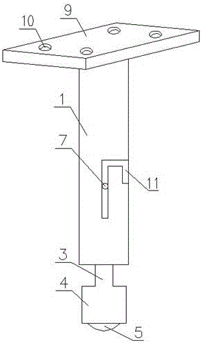
[0023] Casters with shock absorption, such as Figure 1-Figure 3 As shown, it includes an outer cylinder 1 and an inner cylinder 2 , the top of the outer cylinder 1 is fixedly connected with a mounting plate 9 , and the bottom of the mounting plate 9 is fixedly connected with a spring 8 , and the spring 8 is located inside the outer cylinder 1 .

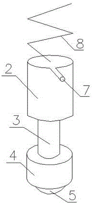
[0024] Such as Figure 1-Figure 3 As shown, the top of the inner cylinder 2 is fixedly connected with the bottom of the spring 8, and the bottom of the inner cylinder 2 is fixedly connected with a connecting rod 3. The connecting rod 3 is made of a metal material with high strength, and is fixed on the connecting rod. The bottom of 3 is fixedly connected with wheel groove 4, and ball 5 is installed in the wheel groove 4.

[0025] The inner cylinder 2 is sleeved in the outer cylinder 1 and can slide freely in one direction in the outer cylinder 1. The user installs the casters on the equipment through the mounting plate. When the equ...

Embodiment 2

[0028] This embodiment is further optimized on the basis of the above embodiments, such as Figure 1-Figure 3 As shown, further, the bottom of the outer cylinder 1 is provided with a positioning plate 6, and the positioning plate 6 is located below the bottom of the inner cylinder 2, and a hole adapted to the connecting rod 3 is provided on the positioning plate 6, and the connecting rod 3 runs through the positioning plate 6.

[0029] Such as Figure 1-Figure 3 As shown, below the positioning plate 6, an outer cylinder extension 12 is also provided along the length direction of the outer cylinder 1, a positioning pin 7 is arranged on the top of the inner cylinder 2, and a side wall of the outer cylinder 1 is provided A pin groove 11 matched with the positioning pin 7 is arranged.

[0030] The length of the pin groove 11 is greater than the length of the connecting rod 3, so that the positioning pin 7 can drive the inner cylinder 2 to slide on the outer cylinder 1, and the l...

Embodiment 3

[0033] This embodiment is further optimized on the basis of the above embodiments, such as Figure 1-Figure 3 As shown, further, the mounting plate 9 is provided with mounting holes 10 through which users can mount the casters on various devices.


PUM


Abstract

The invention discloses a castor with a damping function. The castor comprises an outer barrel, an inner barrel and a ball. An installation plate is arranged at the top of the outer barrel. The inner barrel is slidably matched with the interior of the outer barrel, and a spring is arranged between the top of the inner barrel and the installation plate. The bottom of the inner barrel is provided with a castor groove with a connecting rod, and the ball is installed in the castor groove. A positioning plate is arranged at the bottom of the outer barrel and located below the bottom of the inner barrel, and a hole matched with the connecting rod is formed in the positioning plate. The outer barrel extends downwards to form an outer barrel extension edge, and the bottom of the outer barrel extension edge is lower than the bottom of the positioning plate. A pin groove is formed in the side wall of the outer barrel, and a positioning pin matched with the pin groove is arranged at the top of the inner barrel. Installation holes are formed in the installation plate. The castor with the damping function has the beneficial effects that equipment can be made to have the damping function when moving on the uneven ground, and the using state can be adjusted according to the requirement of a user.

Description

technical field [0001] The invention relates to a caster, in particular to a caster with shock-absorbing function. Background technique [0002] Casters include movable casters and fixed casters. Swivel casters are commonly referred to as universal wheels. Its structure can rotate 360°, while fixed casters are also called directional casters. It has no rotating structure and cannot rotate. With the continuous development of modern technology, more and more different casters are used for various equipment. Ordinary casters do not have the function of shock absorption. When the equipment moves on uneven ground, it is easy to cause damage to the equipment, which is not conducive to protection of equipment. [0003] Therefore, it is a technical problem to be solved by those skilled in the art to design a caster with a shock-absorbing function when the equipment can be moved on uneven ground. Contents of the invention [0004] The purpose of the present invention is to provid...

Claims


Application Information

Patent Timeline
Patent Type & Authority Applications(China)
IPC IPC(8): B60B33/04
CPCB60B33/045
Inventor 付裕
Owner CHENGDU DIANSHI CREATIVE TECH
Why Eureka
Try Eureka