Method for Calculating Dynamic Reserves of Fracture-vuggy Reservoirs

A technology of dynamic reserves and fracture-vug type, applied in calculation, data processing applications, instruments, etc., can solve the problems of reservoir space division, time and economic loss, poor accuracy, etc., achieve accurate reservoir scale, avoid particularity, The effect of high accuracy

Active Publication Date: 2020-03-27
恒泰艾普(北京)能源科技研究院有限公司 +1
View PDF6 Cites 0 Cited by
  • Summary
  • Abstract
  • Description
  • Claims
  • Application Information

AI Technical Summary

Problems solved by technology

[0003] At present, the calculation of dynamic reserves of reservoirs mostly adopts pressure drop curve method, pressure drop recovery curve method, water drive curve method, decline curve method, material balance method and well testing method, etc. Among them, the well testing method is only applicable to the early stages of reservoir development. The closed elastic drive of constant volume, and the well test curve obtained by fitting the well test data to obtain the calculation formula of dynamic reserves is complex, which will lead to low calculation accuracy of dynamic reserves; the material balance method is not based on the storage space of the reservoir to be developed Therefore, the simplified material balance equation is often rough in quality and does not conform to the actual situation, resulting in low calculation accuracy and large deviation of dynamic reserves; in addition, the pressure drop curve method, pressure drop recovery curve method, water drive curve method and decline The curve method and other methods are used to obtain dynamic reserve calculation formulas based on various curves. The method is complex and the calculation process is cumbersome. Errors caused by human calculations and errors in the actual development data of the reservoir can easily lead to low calculation accuracy of dynamic reserves. Bring errors and unnecessary time and economic losses to reservoir development and adjustment

Method used


Image

  • Method for Calculating Dynamic Reserves of Fracture-vuggy Reservoirs
  • Method for Calculating Dynamic Reserves of Fracture-vuggy Reservoirs
  • Method for Calculating Dynamic Reserves of Fracture-vuggy Reservoirs

Examples


Embodiment Construction

[0017] A method for calculating the dynamic reserves of a fractured-vug reservoir according to the present invention comprises the following steps:

[0018] S01: Bottom-hole crude oil density ρ for the first pressure measurement 1 ;

[0019] S02: The oil well is developed for a period of time, and the cumulative oil production during the period is recorded as N p ;

[0020] S03: The density of crude oil at the bottom of the second pressure measurement ρ 2 ;

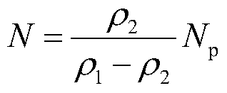
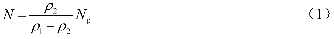
[0021] S04: The measured ρ 1 , ρ 2 and N p Substitute into formula (1) to obtain the dynamic reserves of fractured-vuggy reservoirs.

[0022]

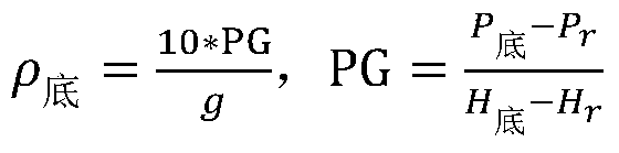
[0023] The bottom hole crude oil density parameter ρ involved in formula (1) 1 , ρ 2 Respectively through the derivation of (2) to obtain

[0024]

[0025] Among them, P 底 is the bottom hole crude oil pressure, P r is the reference point crude oil pressure, H 底 is the bottom depth, H r is the reference point depth. The closer the selected reference point is to...


PUM


Abstract

A fracture-vug type oil reservoir dynamic reserve calculation method provided by the present invention relates to a method for calculation aiming at the oil reservoir reserves of the elastic drive stages, and aims to realize the effects that the needed calculation parameters are less, the parameter values are all measured at an oil recovery site and are objective and accurate, and the calculation results are more credible. The fracture-vug type oil reservoir dynamic reserve calculation method of the present invention comprises the following steps of S01 measuring the bottom hole crude oil density rho 1 for the first time by a manometry method; S02 exploiting an oil well for a period of time, and recording the cumulative oil production as Np; S03, measuring the bottom hole crude oil density rho 2 for the second time by the manometry method; S04 substituting the measured rho 1, rho 2 and the Np into a formula to obtain the fracture-vug type oil reservoir dynamic reserves.

Description

technical field [0001] The invention relates to a method for calculating oil reservoir reserves, in particular to a method for calculating oil reservoir reserves in the elastic flooding stage. Background technique [0002] Ordovician carbonate reservoirs in the Halahatang Oilfield in the Tarim Basin are typical fractured-vuggy reservoirs. The reservoir space is dominated by fractures and caves, with strong heterogeneity, variable fluid properties, and fluid distribution. Oil-water relationship is complex and other characteristics. In addition to reservoir space type and structural characteristics, development well pattern and technical policies, the key factors affecting reservoir development characteristics are the scale of fractured-vuggy units. How to accurately calculate the dynamic reserves of fractured-vuggy units has become a difficult problem. [0003] At present, the calculation of dynamic reserves of reservoirs mostly adopts pressure drop curve method, pressure dr...

Claims


Application Information

Patent Timeline
Patent Type & Authority Patents(China)
IPC IPC(8): G06Q50/06
CPCG06Q50/06
Inventor 王连山孙银行张卫国张茂孙庚文汤承锋
Owner 恒泰艾普(北京)能源科技研究院有限公司
Why Eureka
Try Eureka