
Scheme stage wing parameter estimation method

A technology for parameter estimation and airfoils, applied in computer-aided design, computing, electrical and digital data processing, etc., to solve problems such as unacceptable modeling and computing time

Active Publication Date: 2016-09-28
XIAN AIRCRAFT DESIGN INST OF AVIATION IND OF CHINA
View PDF4 Cites 16 Cited by
  • Summary
  • Abstract
  • Description
  • Claims
  • Application Information

AI Technical Summary

Problems solved by technology

[0002] The performance of an aircraft mainly depends on two basic aspects, the first is the engine, and the second is the wing design, both of which are indispensable. The wing design in the scheme stage mainly refers to the later stage of the wing concept design and the wing structure. In the preliminary design stage, it is necessary to choose between different design schemes, and the shape or configuration design variables are constantly changing. In the prior art, the traditional finite element method is often used to evaluate the impact of structural changes on the aeroelastic characteristics of the wing. The modeling and calculation time it brings will be unacceptable. Therefore, a more convenient and effective method is needed to estimate the structural parameters of the wing. Specifically, a more convenient and effective way is needed to estimate the Wing mass, center of gravity and other structural parameters, at the same time, it is necessary to obtain the wing stiffness distribution that meets the constraints

Method used


Image

  • Scheme stage wing parameter estimation method
  • Scheme stage wing parameter estimation method
  • Scheme stage wing parameter estimation method

Examples


Embodiment Construction

[0033] In order to make the objectives, technical solutions and advantages of the present invention clearer, the technical solutions in the embodiments of the present invention will be described in more detail below in conjunction with the drawings in the embodiments of the present invention. In the drawings, the same or similar reference numerals denote the same or similar elements or elements having the same or similar functions throughout. The described embodiments are some, but not all, embodiments of the invention. The embodiments described below by referring to the figures are exemplary and are intended to explain the present invention and should not be construed as limiting the present invention. Based on the embodiments of the present invention, all other embodiments obtained by persons of ordinary skill in the art without creative efforts fall within the protection scope of the present invention. Embodiments of the present invention will be described in detail below ...


PUM


Abstract

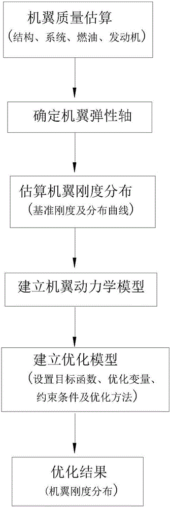
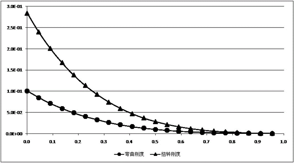
The invention relates to a scheme stage wing parameter estimation method and belongs to the field of wing aeroelasticity design. The method includes the steps that the mass of a wing is determined; root bending rigidity and root torsional rigidity of the wing are calculated; the axial position of an elastic shaft of the wing is determined; bending rigidity distribution of the elastic shaft of the wing and torsional rigidity distribution of the elastic shaft of the wing are determined; a wing dynamical model is built; an optimization module is built according to the wing dynamic model to obtain optimal elastic shaft rigidity distribution, and the optimization module takes minimum wing beam equivalent volume of the wing as an objective function and wing root rigidity distribution in the third step and curve shape parameters of elastic shaft rigidity distribution in the fifth step as variables for optimization. Through the method, rigidity and mass distribution of the wing are obtained quickly, and the dynamic model of the wing is built.

Description

technical field [0001] The invention belongs to the field of wing aeroelastic design, and in particular relates to a method for estimating wing parameters in the scheme stage. Background technique [0002] The performance of the aircraft mainly depends on two basic aspects, the first is the engine, and the second is the wing design, both of which are indispensable. The wing design in the scheme stage mainly refers to the later stage of the wing concept design and the wing structure. In the preliminary design stage, it is necessary to choose between different design schemes, and the shape or configuration design variables are constantly changing. In the prior art, the traditional finite element method is often used to evaluate the impact of structural changes on the aeroelastic characteristics of the wing. The modeling and calculation time it brings will be unacceptable. Therefore, a more convenient and effective method is needed to estimate the structural parameters of the w...

Claims


Application Information

Patent Timeline
IPC IPC(8): G06F17/50
CPCG06F30/15G06F30/367G06F2113/28
Inventor 陈海黄国宁马翔龚亮孙晓红
Owner XIAN AIRCRAFT DESIGN INST OF AVIATION IND OF CHINA
Learn More