Five-stage coupling bridge

A technology of electric bridge and coupling area, which is applied in the direction of circuits, electrical components, connecting devices, etc., can solve the problems of high processing precision, difficulty in practical use, difficulty in ensuring the rigidity of strip lines, etc., and achieve the effect of reducing the precision of processing requirements

Inactive Publication Date: 2016-09-28
ANHUI XINBANG PLASTIC CO LTD
View PDF5 Cites 0 Cited by
  • Summary
  • Abstract
  • Description
  • Claims
  • Application Information

AI Technical Summary

Problems solved by technology

[0003] 1. Microstrip line design, its bandwidth is limited, and it is generally difficult to exceed four times the frequency;
[0004] 2. The design of the stripline cavity also faces bandwidth limitations, and it is difficult to exceed the frequency of 700-2700MHz. Once the bandwidth is widened and the stripline is lengthened, the rigidity of the stripline is difficult to guarantee, and it is easy to deform. The actual trial-produced product and The difference in simulation is huge, and it is difficult to be practical, because the coupling area of ​​the bridge is very tight, so it is much more difficult to design the coupler with different frequencies;
[0005] 3. Columnar coupling rod design, although its bandwidth can cover 350-2700MHz, but its processing requires high precision, complex assembly, and high cost, which greatly limits the application of this type of product

Method used


Image

  • Five-stage coupling bridge
  • Five-stage coupling bridge

Examples


Embodiment Construction

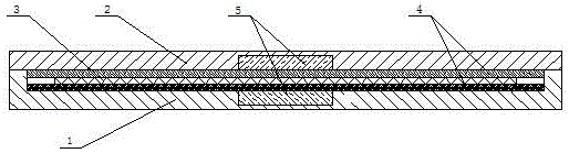
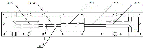
[0015] refer to Figure 1-2 , a five-level coupling bridge, which is composed of a cavity 1, a cover plate 2, a circuit board 3, a dielectric plate 4, and an additional dielectric plate 5. A cover plate 2 is installed above the cavity 1, and a circuit is arranged in the cavity 1. Board 3, a microstrip line 6 is respectively arranged on the upper and lower sides of the circuit board 3, and the four ends of the microstrip line 6 can be connected to the outside through the cavity 1, and the upper and lower sides of the circuit board 3 are respectively provided with a dielectric board 4, and the dielectric board 4 are respectively provided with additional dielectric plates 5, and the microstrip lines 6 are composed of a first-level coupling area 6.1, a second-level coupling area 6.2, a third-level coupling area 6.3, a fourth-level coupling area 6.4, and a fifth-level coupling area 6.5 , from a top view, the first-level coupling regions 6.1 of the two microstrip lines 6 are coincid...


PUM


Abstract

Provided is a five-stage coupling bridge, relating to the technical field of bridges. The five-stage coupling bridge includes a cavity body, a cover board, a circuit board, dielectric plates, and additional dielectric plates, the cover plate is arranged on the cavity body, the circuit board is arranged in the cavity body, the upper and lower surfaces of the circuit board are respectively provided with microstrip lines, the four ends of the microstrip lines are connected to the outside via the cavity body, the dielectric plates are arranged above and under the circuit board, and the outer sides of the dielectric plates are respectively provided with the additional dielectric plate. The invention adopts the five-stage microstrip line symmetrical design of the coupling strip line, so that not only the requirement of bandwidth coverage of a general cylindrical coupling bar bridge is met, but also the situations that the strip lines are too long and the rigidity and deformation cannot be guaranteed are changed; and moreover, the machining requirement precision, assembling requirement, and production cost of the production process are reduced.

Description

Technical field: [0001] The invention relates to the technical field of electric bridges, in particular to a microstrip line electric bridge. Background technique: [0002] The frequency of the widely used 3dB bridge is between 800-2500MHz. This frequency covers the main frequency of mobile communication, and also covers the general frequency of 3G. Due to the popularization of digital TV, the original analog signal gradually cancels the frequency of 700MHz. It may be used in 3G products. If you want full-band coverage, you need bridges and power splitters with wider bandwidths to cover more frequency bands. Existing bridges generally use the following designs , but each has its own drawbacks: [0003] 1. Microstrip line design, its bandwidth is limited, and it is generally difficult to exceed four times the frequency; [0004] 2. The design of the stripline cavity also faces bandwidth limitations, and it is difficult to exceed the frequency of 700-2700MHz. Once the bandwi...

Claims


Application Information

Patent Timeline
Patent Type & Authority Applications(China)
IPC IPC(8): H01P5/12
CPCH01P5/12
Inventor 戴爱谷
Owner ANHUI XINBANG PLASTIC CO LTD
Why Eureka
Try Eureka