
Camera lens and camera device

A camera lens and lens group technology, applied in optical components, instruments, optics, etc., can solve the problems that are not conducive to shortening the full length of the lens and miniaturization of the camera lens, and achieve the effect of high resolution

Active Publication Date: 2021-03-09
FUJIFILM CORP
View PDF4 Cites 0 Cited by
  • Summary
  • Abstract
  • Description
  • Claims
  • Application Information

AI Technical Summary

Problems solved by technology

[0011] In addition, the overall lens length of the imaging lens described in Patent Document 4 is too short relative to the focal length of the entire system. Therefore, shortening the overall lens length is not conducive to miniaturization of the imaging lens and correction of various aberrations.

Method used


Image

  • Camera lens and camera device
  • Camera lens and camera device
  • Camera lens and camera device

Examples


Embodiment 1

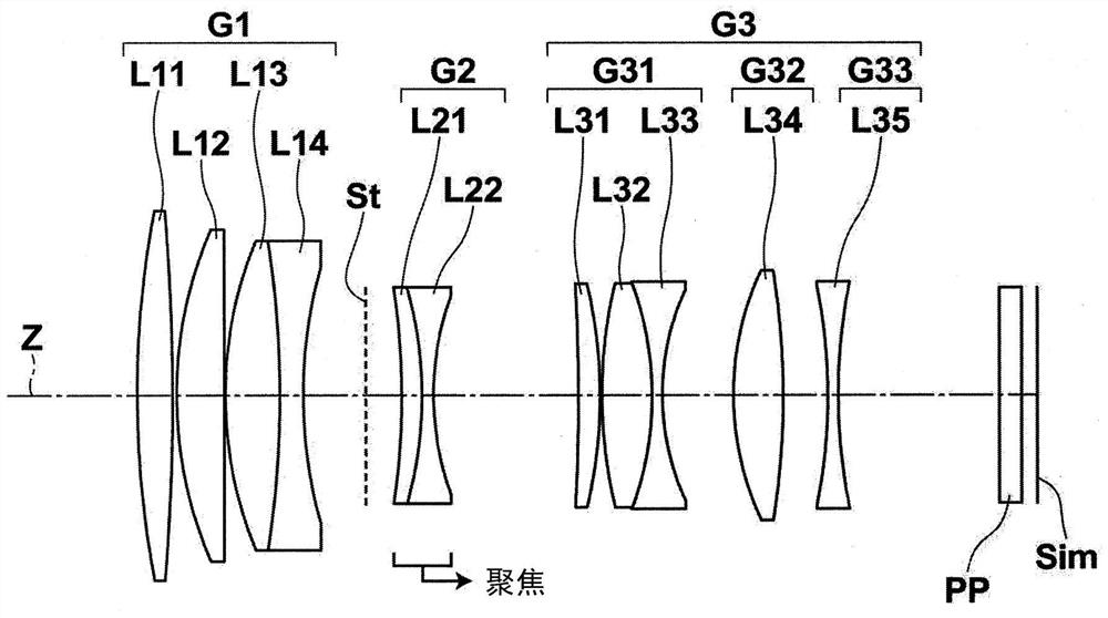
[0221] figure 1 The arrangement of the lens groups of the imaging lens of Example 1 is shown. It should be noted, figure 1 The detailed description of the lens group and each lens in the structure is as above, therefore, unless otherwise required, repeated descriptions will be omitted below.

[0222] Table 1 shows basic lens data of the imaging lens of Example 1. Here, the optical member PP is also shown together. In Table 1, the column of Si shows the surface numbers when the component elements are assigned surface numbers such that the object-side surface of the component located closest to the object side is the first and gradually increases toward the image side. The i-th (i=1, 2, 3, . . . ) face number. The column of Ri shows the radius of curvature of the i-th surface, and the column of Di shows the distance between the i-th surface and the i+1-th surface on the optical axis Z. It should be noted that, when the inter-plane interval is one that varies due to focusing...

Embodiment 2

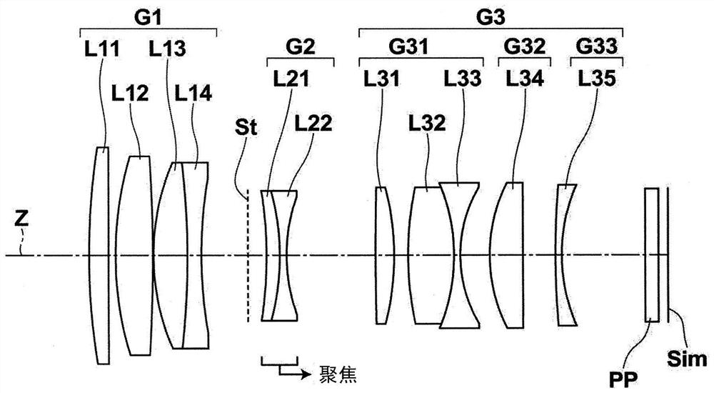
[0240] figure 2 The arrangement of lens groups in the imaging lens of Example 2 is shown. Tables 3 and 4 show basic lens data and various factor data of the imaging lens of Example 2, respectively. in addition, Figure 9 Various aberration diagrams of the imaging lens of Example 2 are shown.

[0241] 【table 3】

[0242] Example 2

[0243]

[0244] 【Table 4】

[0245] Example 2

[0246] infinity recent f 87.029 Bf 21.880 FNo. 2.06 2.37 2ω 19.0 16.6 β 0.00 0.14 DD[8] 4.000 12.982 DD[11] 19.250 10.268

Embodiment 3

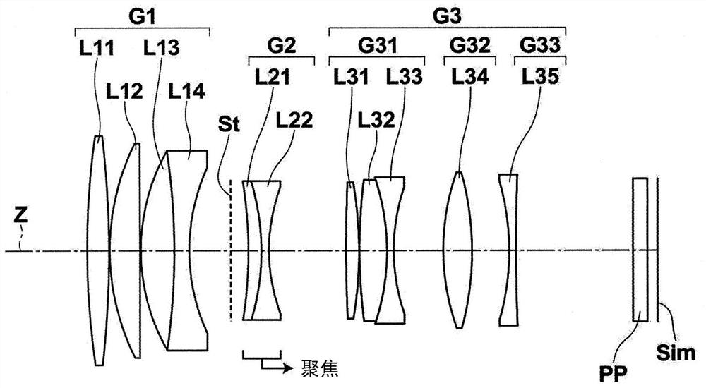
[0248] image 3 The arrangement of lens groups in the imaging lens of Example 3 is shown. Tables 5 and 6 show the basic lens data and various factor data of the imaging lens of Example 3, respectively. in addition, Figure 10 Various aberration diagrams of the imaging lens of Example 3 are shown.

[0249] 【table 5】

[0250] Example 3

[0251]

[0252] 【Table 6】

[0253] Example 3

[0254] infinity recent f 90.000 Bf 27.281 FNo. 2.05 2.34 2ω 18.4 16.0 β 0.00 0.14 DD[8] 3.500 11.216 DD[11] 15.500 7.784


PUM


Abstract

The present invention provides an imaging lens that realizes miniaturization of the imaging lens and reduction of aberration variation caused by focusing, and has good optical performance, and an imaging device using the imaging lens. The imaging lens is composed of a first lens group (G1) with positive refractive power, a second lens group (G2) with negative refractive power, and a third lens group (G3) with positive refractive power in order from the object side, The second lens group (G2) has more than one positive lens and more than one negative lens, in the state where the first lens group (G1) and the third lens group (G3) are fixed relative to the imaging surface, the first lens group (G1) and the third lens group (G3) are fixed. The second lens group (G2) moves from the object side to the image side along the optical axis, thereby performing focusing from an object at infinity to an object at the shortest distance, and this imaging lens satisfies predetermined conditional expressions (1) and conditional expressions (2) .

Description

technical field [0001] The present invention relates to an imaging lens, and more particularly relates to an imaging lens for medium-range telephoto photography or telephoto photography suitable for imaging devices such as digital cameras. In addition, the present invention relates to an imaging device including the imaging lens described above. Background technique [0002] In recent years, an imaging lens employing an inner focus method has been used as a medium-range telephoto lens or a telephoto lens used in an imaging device such as a digital camera. For example, Patent Documents 1 to 4 disclose imaging lenses that adopt a three-group structure consisting of a first lens group, a second lens group, and a third lens group, and when the first lens group and the third lens group are compared to Focusing is performed by moving the second lens group relative to the imaging plane while the imaging plane is fixed. [0003] prior art literature [0004] Patent Document 1: Ja...

Claims


Application Information

Patent Timeline
Patent Type & Authority Patents(China)
IPC IPC(8): G02B15/173G02B13/02
CPCG02B13/02G02B15/173G02B9/64
Inventor 河村大树
Owner FUJIFILM CORP
Learn More