
Secondary voltage regulator circuit

A technology of voltage stabilizing circuits and resistors, applied in electrical components, adjusting electrical variables, and output power conversion devices, etc., can solve problems such as increased loss, reduced power efficiency, and inability to achieve small size.

Active Publication Date: 2019-06-14
广州森万象新材料科技有限公司
View PDF2 Cites 0 Cited by
  • Summary
  • Abstract
  • Description
  • Claims
  • Application Information

AI Technical Summary

Problems solved by technology

However, the wiring low-dropout voltage regulator increases the loss and reduces the power supply efficiency; it also needs a radiator to dissipate heat, which cannot meet the requirements of small size; and in standby mode, additional switches or more expensive special linear low-dropout voltage regulators are required. compressor, but also can not meet the "Energy Star" energy-saving certification indicators

Method used


Image

  • Secondary voltage regulator circuit
  • Secondary voltage regulator circuit

Examples


Embodiment Construction

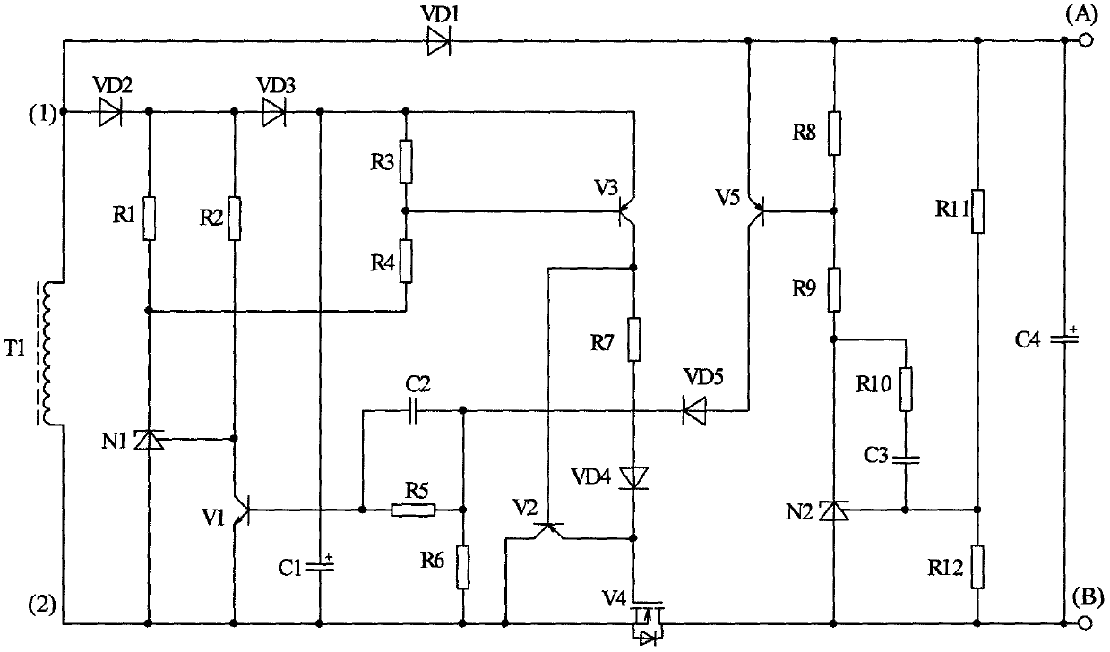
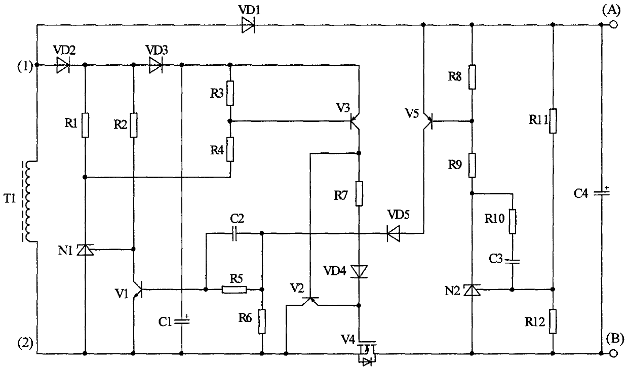
[0007] figure 1 It is an embodiment of the secondary voltage stabilizing circuit of the present invention, and the drawings and the invention will be further explained below in conjunction with the embodiment.

[0008] Describe the specific design of the secondary voltage regulator circuit first. figure 1 T1 is an auxiliary output winding of the switching transformer. One end (1) of the auxiliary output winding T1 is connected to the positive pole of the diode VD1, and the negative pole of the diode VD1 is the positive pole (A) of the output DC voltage; the other end (2) of the output winding T1 ) is connected to the source of an N-channel FET V4, the drain of V4 is the negative pole (B) of the output DC voltage, and the negative pole (B) of the DC voltage is used as the reference zero potential of the secondary voltage stabilizing circuit.

[0009] figure 1 The N1 and N2 components in the model are TL431, which are three-terminal adjustable precision voltage references. The...


PUM


Abstract

The invention provides a secondary voltage-stabilizing circuit, and belongs to the technical field of switching power supplies, which provides a switching power supply for outputting multiple paths of low-voltage DC. Normally, only the main output voltage of a switching power supply is subjected to the voltage stabilization control, while the other paths of the auxiliary output voltages of the switching power supply are not stable. The secondary voltage-stabilizing circuit is connected with the auxiliary output winding of a switching transformer, so that the auxiliary output voltage of the switching power supply is stabilized. The secondary voltage-stabilizing circuit can be applied to switching power supplies capable of being automatically adapted to various circuit topological forms. According to the technical scheme of the invention, the secondary voltage-stabilizing circuit is integrated based on the micro electronic technique, and has fewer external elements. Therefore, the secondary voltage-stabilizing circuit is low in cost, small in size, high in voltage-stabilizing precision, low in loss, free of external drive and good in electromagnetic compatibility. All the paths of output voltages can be operated in the non-common-ground manner. The maximum allowable operating voltages of the integrated secondary voltage-stabilizing circuit are composed of three levels, namely 30V, 60V and 100V. The output currents of the integrated secondary voltage-stabilizing circuit are composed of three levels, namely 1A, 2A and 3A. Therefore, a series of products are formed. The secondary voltage-stabilizing circuit with the output current to be 3A is in the form of a non-standardized DIP-10 package, while rest secondary voltage-stabilizing circuits are in the form of DIP-8 standardized packages.

Description

technical field [0001] The invention relates to a secondary voltage stabilizing circuit, which belongs to the technical field of switching power supplies and is applied to a switching power supply outputting multiple low-voltage direct currents. The secondary voltage stabilizing circuit is connected to an auxiliary output winding of a switching transformer to stabilize the auxiliary output voltage of the switching power supply. , It can automatically adapt to the switching power supply in various circuit topologies for auxiliary output voltage regulation. Background technique [0002] Many electrical products, such as LCD-TV, PC, set-top box, communication power supply, cordless phone, instrumentation, etc., require low-voltage DC power supply with more than two voltages; The AC mains is transformed into several voltages of low-voltage DC power supply for its power supply. One of the output voltages bears most of the power requirements of electrical products, or the output ...

Claims


Application Information

Patent Timeline
Patent Type & Authority Patents(China)
IPC IPC(8): H02M3/156
Inventor 何曙光
Owner 广州森万象新材料科技有限公司
Learn More