
Detection system and detection method for camera module group

A camera module and detection system technology, which is applied in image communication, television, electrical components, etc., can solve the problems of not being able to meet a large field of view, not being able to detect the performance of the camera module, and having a large space

Active Publication Date: 2016-10-05
NINGBO SUNNY OPOTECH CO LTD
View PDF8 Cites 14 Cited by
  • Summary
  • Abstract
  • Description
  • Claims
  • Application Information

AI Technical Summary

Problems solved by technology

Due to the small field of view of ordinary camera modules, the area of ​​the planar light source does not need to be too large, but for wide-angle camera modules, ordinary planar light sources cannot meet the large field of view, especially when the field of view is greater than 120 degrees , the area of ​​the light source required is getting bigger and bigger, and the space needed is getting bigger and bigger. When the field of view exceeds 180 degrees, it is impossible to use a flat light source to detect the relevant performance of the camera module.

Method used


Image

  • Detection system and detection method for camera module group
  • Detection system and detection method for camera module group
  • Detection system and detection method for camera module group

Examples


Embodiment Construction

[0054] The following description serves to disclose the present invention to enable those skilled in the art to carry out the present invention. The preferred embodiments described below are only examples, and those skilled in the art can devise other obvious variations. The basic principles of the present invention defined in the following description can be applied to other embodiments, variations, improvements, equivalents and other technical solutions without departing from the spirit and scope of the present invention.

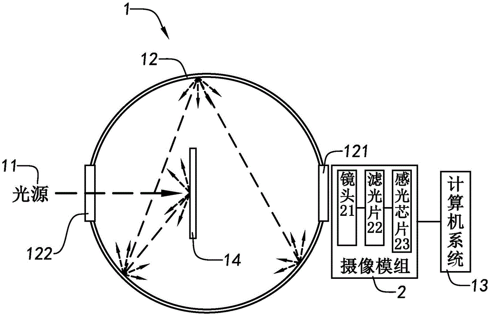
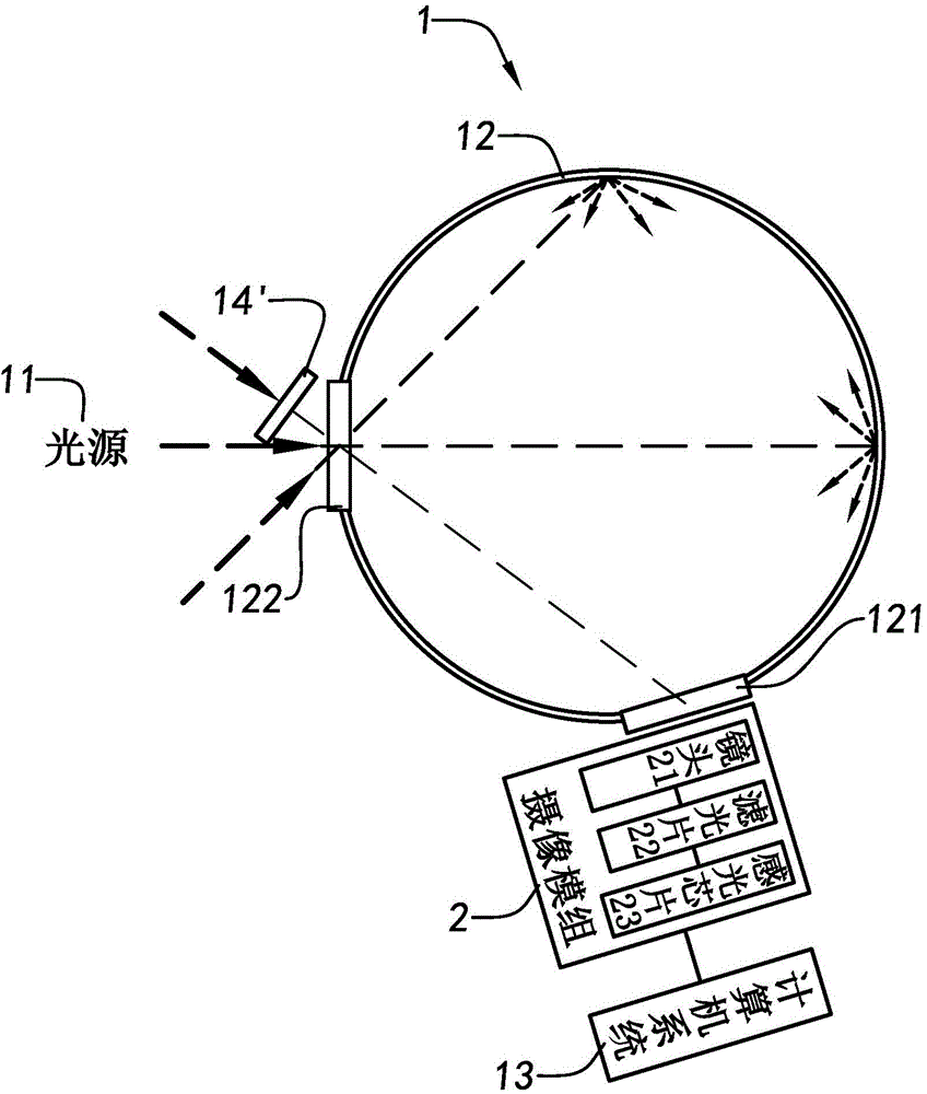
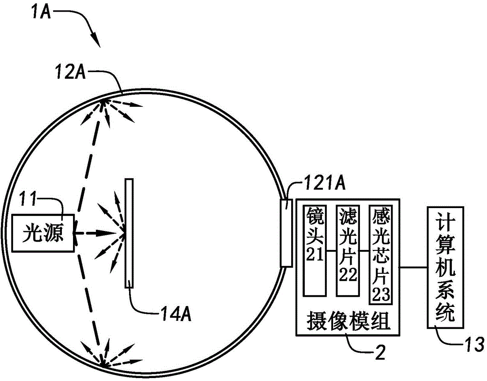
[0055] The camera module testing system 1 of the present invention can provide a light source with uniform brightness when performing imaging performance testing on a camera module 2 . The imaging performance testing includes stain detection, brightness uniformity testing, and the like. The testing system 1 includes a light source 11 and an integrating sphere 12 .

[0056] The integrating sphere 12 is used to homogenize the light emitted by the light sou...


PUM


Abstract

The invention provides a detection system and detection method for a camera module group, and a method for providing a uniform light source for the camera module group. The detection system that is suitable for carrying out imaging performance detection on a camera module group consists of a light source and an integrating sphere having an output port; the light emitted by the light source enters the integrating sphere, so that a uniform light beam is obtained at the output port; and the output port is suitable for setting the camera module group, so that the light beam can enter the camera module group for imaging.

Description

technical field [0001] The invention relates to the field of camera modules, in particular to a camera module detection system and detection method. Background technique [0002] With the advancement of technology, people's requirements are getting higher and higher, so there are more and more fields that need to use wide-angle camera modules. A wide-angle camera module refers to a camera module with a field of view greater than 90 degrees. The size of the field of view determines the field of view of the camera module, the larger the field of view, the larger the field of view. Target objects beyond the field of view will not be received into the lens. The field of view of an ordinary camera module is usually about 30 degrees, and it can be seen that the field of view of a wide-angle camera module is much larger than that of an ordinary camera module. [0003] Usually, the method of detecting the stained spots and brightness uniformity of a camera module is to place a un...

Claims


Application Information

Patent Timeline
IPC IPC(8): H04N17/00
Inventor 张扣文鲁丁柳高烽卢鹏
Owner NINGBO SUNNY OPOTECH CO LTD
Learn More