Cartridge unloading method

A kind of tray and bottom technology, which is applied in the field of tray lower and can solve the problems such as the inaccurate insertion of the fork plate and the inaccurate separation of the tray.

Active Publication Date: 2018-01-26
CHENGDU SOONTRUE MECHANICAL EQUIP CO LTD
View PDF15 Cites 0 Cited by
  • Summary
  • Abstract
  • Description
  • Claims
  • Application Information

AI Technical Summary

Problems solved by technology

[0005] In order to overcome the problem that the fork plate cannot be accurately inserted between adjacent trays in the actual application of the existing box lowering mechanism, resulting in the inability to accurately separate the trays, a method for lowering the tray with trays is now proposed

Method used


Image

  • Cartridge unloading method
  • Cartridge unloading method
  • Cartridge unloading method

Examples


Embodiment 1

[0075] A method for unloading a tray, characterized in that it comprises the following steps:

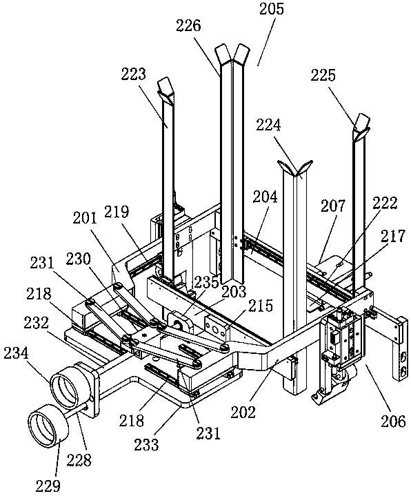
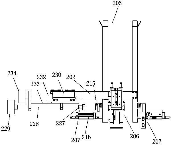
[0076] A. Place the stacked trays in the tray storage space surrounded by the guard plate 205;

[0077] B. At least one fork plate 217 is provided on each of the front, back, left and right sides of the tray storage space, and the two fork plates 217 provided in the front and rear directions are the first group of fork plates 217, and the left and right directions are provided The two fork plates 217 are the second set of fork plates 217, and one set of fork plates 217 in the two sets of fork plates 217 is the rotating fork plate 206. The edge support of the box; the other set of fork plates 217 in the two sets of fork plates 217 is a horizontal fork plate 207, and its working principle is to realize the support to the edge of the tray box by doing horizontal reciprocating motion. When the initial position, rotate the fork plate 206 Hold the tray, the horizontal fork plate 207 does...

Embodiment 2

[0085] A method for unloading a tray, characterized in that it comprises the following steps:

[0086] A. Place the stacked trays in the tray storage space surrounded by the guard plate 205;

[0087] B. At least one fork plate 217 is provided on each of the front, back, left and right sides of the tray storage space, and the two fork plates 217 provided in the front and rear directions are the first group of fork plates 217, and the left and right directions are provided The two fork plates 217 are the second set of fork plates 217, and one set of fork plates 217 in the two sets of fork plates 217 is the rotating fork plate 206. The edge support of the box; the other set of fork plates 217 in the two sets of fork plates 217 is a horizontal fork plate 207, and its working principle is to realize the support to the edge of the tray box by doing horizontal reciprocating motion. When the initial position, rotate the fork plate 206 Hold the tray, the horizontal fork plate 207 does...

Embodiment 3

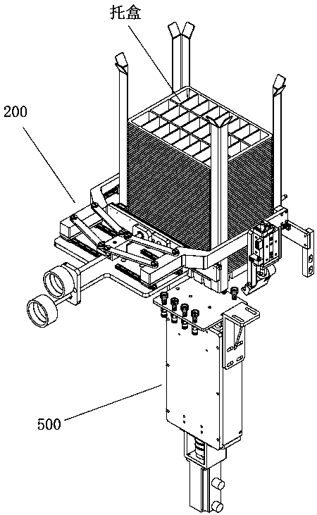
[0097] On the basis of Embodiment 1 or 2, the equipment for realizing the method is a box-down mechanism including a bracket and an adjustable box-loading frame 200, the adjustable box-loading frame 200 is arranged on the bracket, and the adjustable box-loading frame 200 is arranged on the bracket. A lifting and absorbing component 500 for absorbing the tray is also arranged below the box loading frame 200, and the lifting and absorbing component 500 is installed on the bracket.

[0098] The working principle of the lower box mechanism: the tray is placed in the box loading frame, and the lowermost tray is absorbed by the lifting and absorbing part 500, and then falls onto the tray conveying pushing part 300, and then the tray conveying pushing part 300 puts the tray into place. The box is pushed in translation to under the tray positioning pushing part 400, and then the tray positioning pushing part 400 pushes the tray down, so that the tray falls onto the subsequent conveyor ...


PUM


Abstract

The invention relates to the fields of mechanical processing and box packing, in particular to a supporting box lowering method. The supporting box lowering method comprises the following steps that A, a plurality of stacked supporting boxes are placed in a supporting box storage space; B, the supporting boxes are supported by rotary fork plates instead of horizontal fork plates; C, a lifting adsorption component ascends to the position below the outer bottom face of the lowermost supporting box and conduct negative pressure adsorption on the bottom face of the lowermost supporting box; D, the lifting adsorption component conducts negative pressure adsorption on the outer bottom face of the lowermost supporting box continuously, moves downwards by a certain distance H and remains still; E, the horizontal fork plates are inserted into the position between the lowermost supporting box and the penultimate supporting box, and the penultimate supporting box is supported; and F, the rotary fork plates rotate downwards around connecting points so as to release the supporting box, the lifting adsorption component continues to move downwards, adsorbs the lowermost supporting box and continues to move downwards, and the supporting box falls onto a conveying belt vertically. The supporting box lowering method aims to solve the problems that the supporting boxes are stacked closely or the horizontal edges of the supporting boxes are not obvious, and the supporting boxes stacked closely can be separated precisely.

Description

technical field [0001] The invention relates to the field of mechanical processing and box packing, in particular to a box-cartoning method. Background technique [0002] In the existing field of mechanical processing and boxing, when the products to be boxed are processed, it is usually necessary to perform boxing operations, but the existing boxing is basically to put the food directly into the tray by hand, and stack The trays together often need to be placed manually so that the products can automatically fall into the trays. [0003] In view of the above situation, the applicant applied for the existing patent for improving the cartoning process. For example, the patent application number is CN201520254060.6, the application date is 2015.04.24, and the practical name is "the unloading mechanism of the food cartoning machine". The new type patent, its technical proposal is: the utility model relates to the field of food processing machinery and equipment, specifically, ...

Claims


Application Information

Patent Timeline
Patent Type & Authority Patents(China)
IPC IPC(8): B65G59/10B65G59/06B65B43/46
CPCB65B43/46B65G59/061B65G59/10B65G2201/025
Inventor 薛博勋彭涛
Owner CHENGDU SOONTRUE MECHANICAL EQUIP CO LTD
Why Eureka
Try Eureka