Lug ring type hydraulic cylinder displacement sensor installation structure

A technology of displacement sensor and installation structure, applied in the field of hydraulic cylinder manufacturing, can solve the problems such as the large volume of the electronic head and the influence of the overall structure of the hydraulic cylinder.

Active Publication Date: 2016-10-12
TIANJIN URANUS HYDRAULIC MACHINERY
View PDF6 Cites 4 Cited by
  • Summary
  • Abstract
  • Description
  • Claims
  • Application Information

AI Technical Summary

Problems solved by technology

[0002] When the hydraulic cylinder adopts a built-in displacement sensor, the electronic head of the sensor needs to be installed on the cylinder bottom of the hydraulic cylinder. However, due to the large size of the electronic head and the need for wiring, its reasonable installation position will affect the overall structure of the hydraulic cylinder. influences

Method used


Image

  • Lug ring type hydraulic cylinder displacement sensor installation structure
  • Lug ring type hydraulic cylinder displacement sensor installation structure

Examples


Embodiment Construction

[0013] Below in conjunction with the examples, the present invention is further described, the following examples are illustrative, not limiting, and the protection scope of the present invention cannot be limited by the following examples.

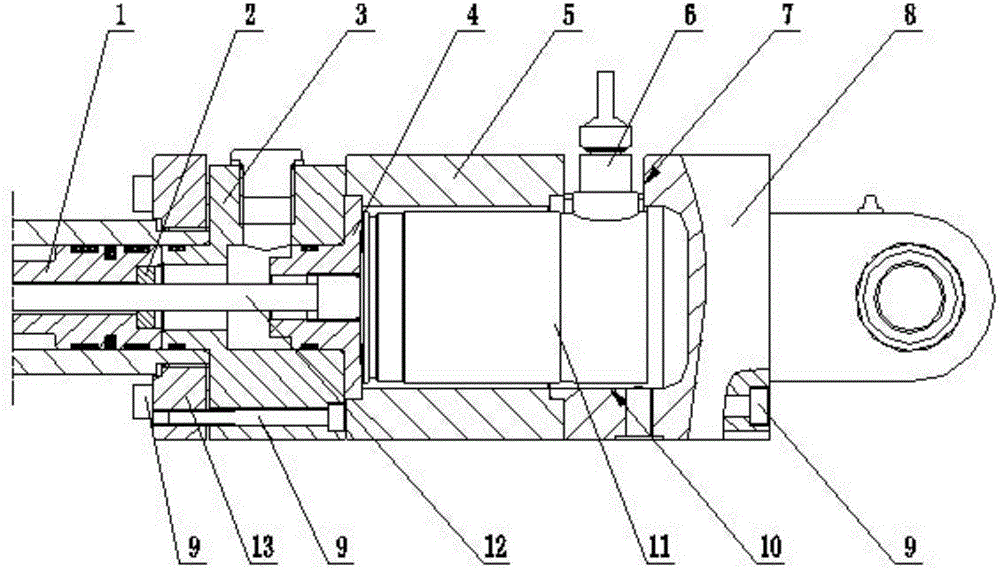
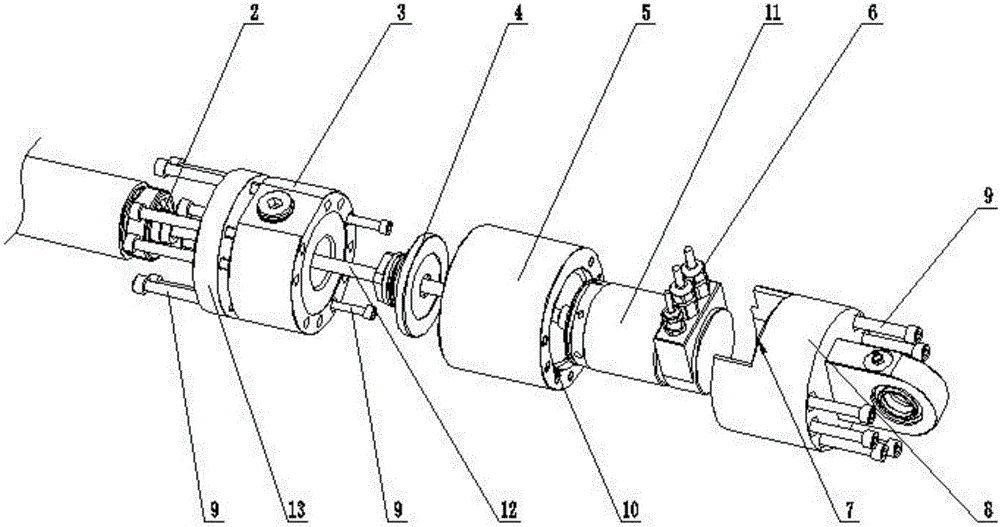
[0014] An earring type hydraulic cylinder displacement sensor installation structure, the innovation of the present invention is that it includes an earring cylinder 5, and the ends on both sides of the earring cylinder respectively pass through the inner hexagonal bolt 9, the flange 13 and the cylinder bottom 3 and the cylinder bottom earrings 8 fixed installation, the cylinder bottom earring, a hollow cavity 10 is formed between the earring cylinder and the inner end surface of the cylinder bottom, the hollow cavity is used to accommodate the electronic head 11 of the displacement sensor, the cylinder bottom earring and the earring A through groove 7 is made in the end side wall of the same side of the cylinder, the through groove commun...


PUM


Abstract

The invention relates to the field of hydraulic cylinder manufacturing, in particular to a lug ring type hydraulic cylinder displacement sensor installation structure. The lug ring type hydraulic cylinder displacement sensor installation structure comprises a lug ring cylinder barrel; the end portions of the two sides of the lug ring cylinder barrel are fixedly installed together with a cylinder bottom and a cylinder bottom lug ring correspondingly; a hollow cavity is formed among the inner side end face of the cylinder bottom lug ring, the inner side end face of the lug ring cylinder barrel and the inner side end face of the cylinder bottom and is internally used for containing an electronic head of a displacement sensor; a through groove is manufactured in the side wall of the end portion, on the same side as the lug ring cylinder barrel, of the cylinder bottom lug ring, communicates with the hollow cavity and is used for a terminal of the contained electronic head to stretch out; the induction end of the displacement sensor is installed together with a piston and a piston rod of a hydraulic cylinder; the end face, located on the same side as the lug ring cylinder barrel, of the cylinder bottom is rotationally provided with a side end portion of an adjusting end cover through a spigot; a thread is manufactured on the other side end portion of the adjusting end cover; the adjusting end cover is fixedly installed together with the electronic head through the thread; a through hole is manufactured in the inner edge of the adjusting end cover; and the interior of the through hole is used for the induction end of the contained displacement sensor to stretch out.

Description

technical field [0001] The invention relates to the field of hydraulic cylinder manufacturing, in particular to an earring type hydraulic cylinder displacement sensor installation structure. Background technique [0002] When the hydraulic cylinder adopts a built-in displacement sensor, the electronic head of the sensor needs to be installed on the cylinder bottom of the hydraulic cylinder. However, due to the large size of the electronic head and the need for wiring, its reasonable installation position will affect the overall structure of the hydraulic cylinder. influences. [0003] On the basis of the above-mentioned hydraulic cylinders, due to the needs of the installation structure of the hydraulic cylinders, the bottom of some hydraulic cylinders needs to adopt an earring structure. However, for the structure of the earring hydraulic cylinder, the installation position of the electronic head is more strict, especially to ensure that both the electronic head and the ea...

Claims


Application Information

Patent Timeline
Patent Type & Authority Applications(China)
IPC IPC(8): F15B15/28
CPCF15B15/2815F15B15/2892
Inventor 梁浩骞王超光刘兵于安才陶娟
Owner TIANJIN URANUS HYDRAULIC MACHINERY
Why Eureka
Try Eureka