
Bath boiler with disinfection function
A boiler and functional technology, used in disinfection, fluid heaters, heating, etc., can solve the problems of unusable, small furnace body, large power consumption, etc., to meet the needs of use, simple and fast operation, and small footprint Effect
- Summary
- Abstract
- Description
- Claims
- Application Information
AI Technical Summary
Problems solved by technology
Method used
Image

Examples
Embodiment 1
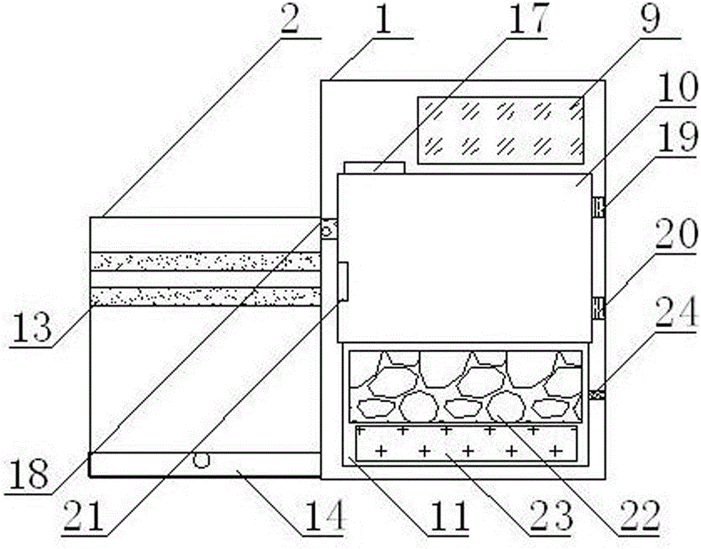
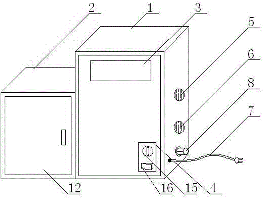
[0015] as the picture shows, A bathing boiler with a disinfection function, comprising a furnace body 1 and a disinfection cabinet 2, a disinfection cabinet 2 is installed at the left end of the furnace body 1, a touch screen 3 is installed at the upper front end of the furnace body 1, and a right side device is installed at the lower front end of the furnace body 1 In the control area 4, the right side of the furnace body 1 is equipped with a water inlet 5, a water outlet 6, a power line 7 and a gas inlet 8 in sequence from top to bottom, and a control box 9 is installed at the upper end of the furnace body 1, and the control box 9 Lower end device water tank 10, described water tank 10 lower end devices combustion chamber 11; Described disinfection cabinet 2 front installation disinfection cabinet cabinet doors 12, described disinfection cabinet 2 inner upper end devices two hanging rods 13, described disinfection cabinet 2 inner bottoms Device cleaning bin 14.
Embodiment 2
[0017] as the picture shows, The fire power adjustment knob 15 is installed at the upper end of the control area 4 , and the ignition switch 16 is installed at the lower end of the control area 4 .
Embodiment 3
[0019] as the picture shows, The temperature sensor 17 is installed on the left side of the top of the water tank 10, the upper left side of the water tank 10 is connected to the disinfection cabinet 2 through a steam pipe 18, the water inlet pipe 19 is installed on the upper right side of the water tank 10, and the water outlet pipe is installed on the lower right side of the water tank 10 20. A water level detector 21 is installed on the left side of the water tank 10 .
PUM
 Abstract
Description
Claims
Application Information