Crown reinforcement for airplane tire

A technology for aircraft tires and reinforcements, applied in aircraft tires, reinforcement layers of pneumatic tires, tire parts, etc., can solve problems such as selection limitations of mechanical stiffness optimization, and achieve the effect of reducing time and improving productivity

Active Publication Date: 2016-10-12
MICHELIN & CO CIE GEN DES ESTAB MICHELIN
View PDF13 Cites 0 Cited by
  • Summary
  • Abstract
  • Description
  • Claims
  • Application Information

AI Technical Summary

Problems solved by technology

Therefore, the limited number of angle values ​​achieved by the number of cycles typically used limits the options for optimizing the mechanical stiffness of the working reinforcement

Method used


Image

  • Crown reinforcement for airplane tire
  • Crown reinforcement for airplane tire
  • Crown reinforcement for airplane tire

Examples


Embodiment Construction

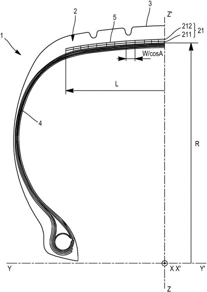
[0045] figure 1 Shows a half view in cross-section of an aircraft tire 1 comprising radially inside the tread 3 and radially on the The working reinforcement 2 on the outside of the body reinforcement 4. Said working reinforcement 2 comprises a working double ply 21 consisting of at least two radially superimposed working layers (211, 212), wound by zigzag circumferentially on a cylindrical laying surface of radius R A strip of width W is obtained, the axis of rotation of the cylindrical paving surface being the axis of rotation (YY') of the tyre. In a radial plane (YZ), each working layer (211, 212) consists of axially juxtaposed sections of the strip 5 having a width W / cosA, where W is the width of the strip 5 (not shown), It is measured perpendicular to the bisector of the strip 5 and A is the angle (not shown) formed by the bisector of the strip 5 with respect to the circumferential direction (XX') in the equatorial plane (XZ).

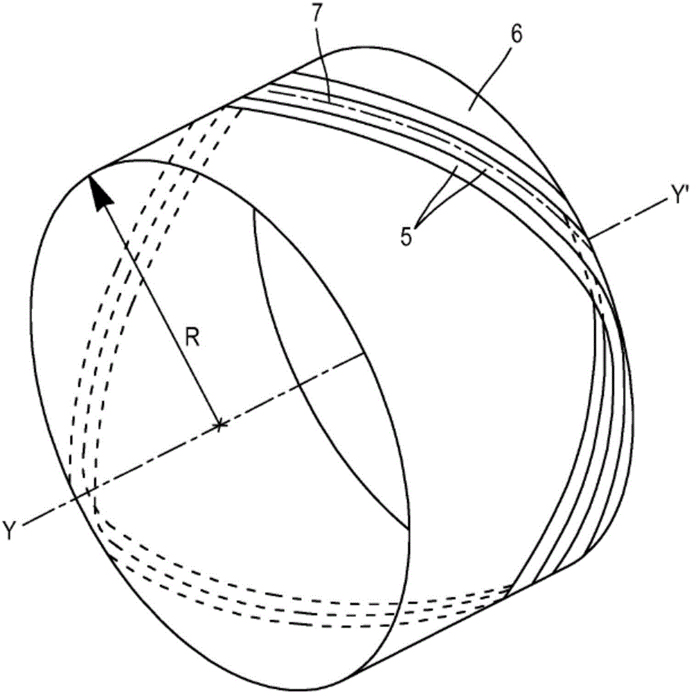
[0046] figure 2 is a perspective view ...


PUM

PropertyMeasurementUnit
widthaaaaaaaaaa
widthaaaaaaaaaa
widthaaaaaaaaaa

Abstract

The present invention relates to an airplane tire and, particularly, to the crown reinforcement thereof. The airplane tire (1) includes a working reinforcement (2) located radially inside a tread (3) and radially outside a carcass reinforcement (4). The working reinforcement (2) includes at least one working dual ply (21) consisting of two radially stacked working layers (211, 212). The working dual ply (21) consists of the circumferential zigzag winding of a strip (5) having a width W over a cylindrical laying surface (6) with radius R and having, for a rotational axis, the rotational axis (YY') of the tire along a periodic curve (7). The periodic curve (7) has a period P and forms an angle A with the circumferential direction (XX') of the tire within the equatorial plane (XZ) of the tire. The circumferential zigzag winding of the strip (5) includes N periods P of the periodic curve (7) over a number T of circumferences 2 Pi R of the cylindrical laying surface (6). According to the invention, the number N of periods P of the periodic curve (7) is an integer that fits the following conditions: (a) N*(W/sin A)=2*Pi*R; (b) N*P=2*Pi*R*T, where T is an integer, (c) N*T is the lowest common multiple of N and T, and the ratio T/N is 1.8 to 2.2.

Description

technical field [0001] The present invention relates to a tire for an aircraft, in particular to a crown reinforcement for an aircraft tyre. Background technique [0002] Hereinafter, circumferential, axial, and radial directions denote directions tangential to the tread surface of the tire in the direction of rotation of the tire, directions parallel to the axis of rotation of the tire, and directions perpendicular to the axis of rotation of the tire, respectively. "Radially inward or radially outward, respectively" means "closer to or farther from the axis of rotation of the tyre, respectively". "Axially inward or axially outward, respectively" means "closer to or farther from, respectively, the equatorial plane of the tire", which is the plane passing through the middle of the tread surface of the tire and perpendicular to the axis of rotation of the tire. [0003] In general, a tire comprises a tread intended to come into contact with the ground via a tread surface conn...

Claims


Application Information

Patent Timeline
Patent Type & Authority Applications(China)
IPC IPC(8): B29D30/30B29D30/70B60C9/26
CPCB29D30/3035B29D30/70B60C9/263B60C2200/02B29K2277/00B60C9/0042B60C2009/1828
Inventor M·罗梅罗德拉奥萨
Owner MICHELIN & CO CIE GEN DES ESTAB MICHELIN
Why Eureka
Try Eureka