A steel pipe automatic correction robot

An automatic calibration and robot technology, which is applied in the field of steel pipe automatic calibration robots and automation equipment, can solve the problems of lack of relatively mature steel tube calibration technology, and achieve the effects of simple structure, convenient operation and low cost

Active Publication Date: 2018-12-04
常熟市创福管业有限公司
View PDF17 Cites 0 Cited by
  • Summary
  • Abstract
  • Description
  • Claims
  • Application Information

AI Technical Summary

Problems solved by technology

[0002] Steel pipe is a common consumable material. At the same time, the straightness of steel pipe plays a key role in its use. At present, there is no mature and highly automated steel pipe correction technology. Therefore, there is an urgent need for an equipment that can automatically correct steel pipes.

Method used


Image

  • A steel pipe automatic correction robot
  • A steel pipe automatic correction robot

Examples


Embodiment Construction

[0011] The present invention will be further described below in conjunction with specific embodiments. The exemplary embodiments and descriptions of the present invention are used to explain the present invention, but not as a limitation to the present invention.

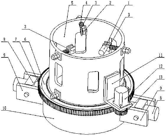
[0012] Such as figure 1 , figure 2 As shown, a steel pipe automatic correction robot includes an annular main frame 5 and a rotating frame 10, a rotating bearing 6, a large gear 7 and a pinion 13, a rotating motor 12 and a rotating motor mounting frame 11, six roller mounting frames 3 and six A roller 2, two roller motors 1, two hydraulic cylinder mounting frames 9, two hydraulic cylinders 8, and two pressure head top blocks 14. The annular main frame 5 is provided with six installation shafts, wherein three installation shafts are evenly distributed on the annular main frame 5 tops, and the other three installation shafts are evenly distributed on the annular main frame 5 bottoms, and are connected with the top t...


PUM


Abstract

The invention discloses a steel pipe automatic correction robot which comprises an annular main rack, a rotating rack, a rotating bearing, a large gear and a small gear, wherein six roller mounting racks are respectively and slidingly mounted on six mounting shafts; six rollers are respectively and rotationally mounted on the six roller mounting racks; two roller motors are respectively mounted on a roller mounting rack at the lower part of and a roller mounting rack at the upper part of the annular main rack; a rotating motor mounting rack is mounted at the external periphery of the annular main rack; a rotating motor is mounted on the rotating motor mounting rack; the rotating bearing is coaxially mounted at the lower part of the annular main rack; the large gear is coaxially mounted on the rotating bearing; cylinder bodies of two hydraulic cylinders are respectively mounted on two hydraulic cylinder mounting racks; piston rods of the two hydraulic cylinders respectively stretch into the rotating rack; and pressing head jacking blocks are mounted at the end parts of the piston rods. Through the arrangement of the automatic rollers and the rotating rack, the purpose of correcting a steel pipe efficiently and automatically is realized. The steel pipe automatic correction robot is simple in structure, low in cost and convenient to operate.

Description

technical field [0001] The invention relates to an automatic equipment, in particular to a steel pipe automatic correction robot, which belongs to the technical field of automatic metallurgical equipment. Background technique [0002] Steel pipe is a common consumable material. At the same time, the straightness of steel pipe plays a key role in its use. At present, there is no mature and highly automated steel pipe correction technology. Therefore, there is an urgent need for an equipment that can automatically correct steel pipes. . Contents of the invention [0003] In view of the above problems, the present invention provides an automatic steel pipe correction robot, which realizes the purpose of efficient and automatic steel pipe correction by being provided with automatic rollers and rotating brackets. [0004] The technical solution adopted by the present invention is: a steel pipe automatic correction robot, including an annular main frame and a rotating frame, a ...

Claims


Application Information

Patent Timeline
Patent Type & Authority Patents(China)
IPC IPC(8): B21D3/14
CPCB21D3/14
Inventor 不公告发明人
Owner 常熟市创福管业有限公司
Why Eureka
Try Eureka