Cross arm and transmission tower
A technology for transmission towers and cross-arms, which is applied in the field of cross-arms and transmission towers, and can solve problems that affect the long-term use of cross-arms, increase production difficulty, and increase manufacturing costs.
- Summary
- Abstract
- Description
- Claims
- Application Information
AI Technical Summary
Problems solved by technology
Method used
Image

Examples
Embodiment 1
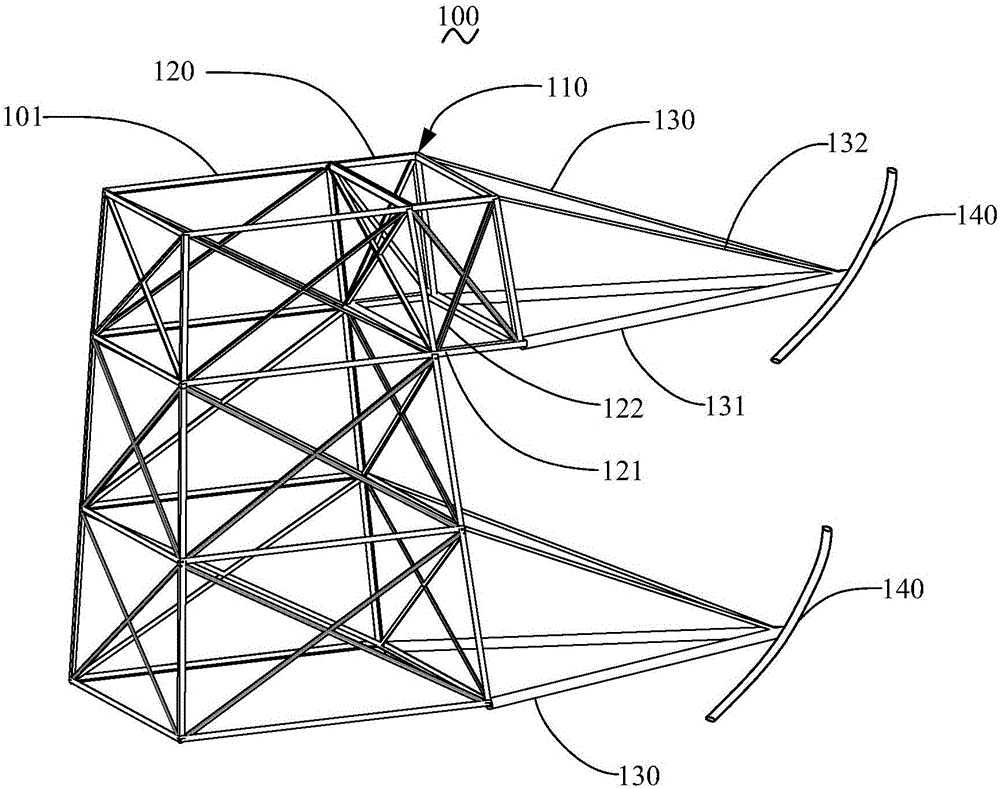
[0020] Such as figure 1 As shown, the transmission tower 100 of Embodiment 1 of the present invention includes a tower body 101, and a cross arm 110 is connected to the tower body 101. The composite cross-arm section 130 , the other end of the composite cross-arm section 130 is used for connecting the wire 140 .
[0021] Specifically, the transmission tower 100 is a lattice transmission tower, figure 1 Middle is a partial three-dimensional schematic diagram of the transmission tower 100 . The metal bracket 120 is a lattice bracket, which can better bear lateral loads. In this embodiment, the metal bracket 120 is in the shape of a cuboid, made of metal such as angle steel, and extends vertically outward along the tower body 101. The metal bracket 120 includes a column limb 121 as a frame and a truss structure for forming a truss structure with the column limb 121. Strip 122. There are eight column limbs 121, including six horizontal ones and two vertical ones, which are con...
Embodiment 2
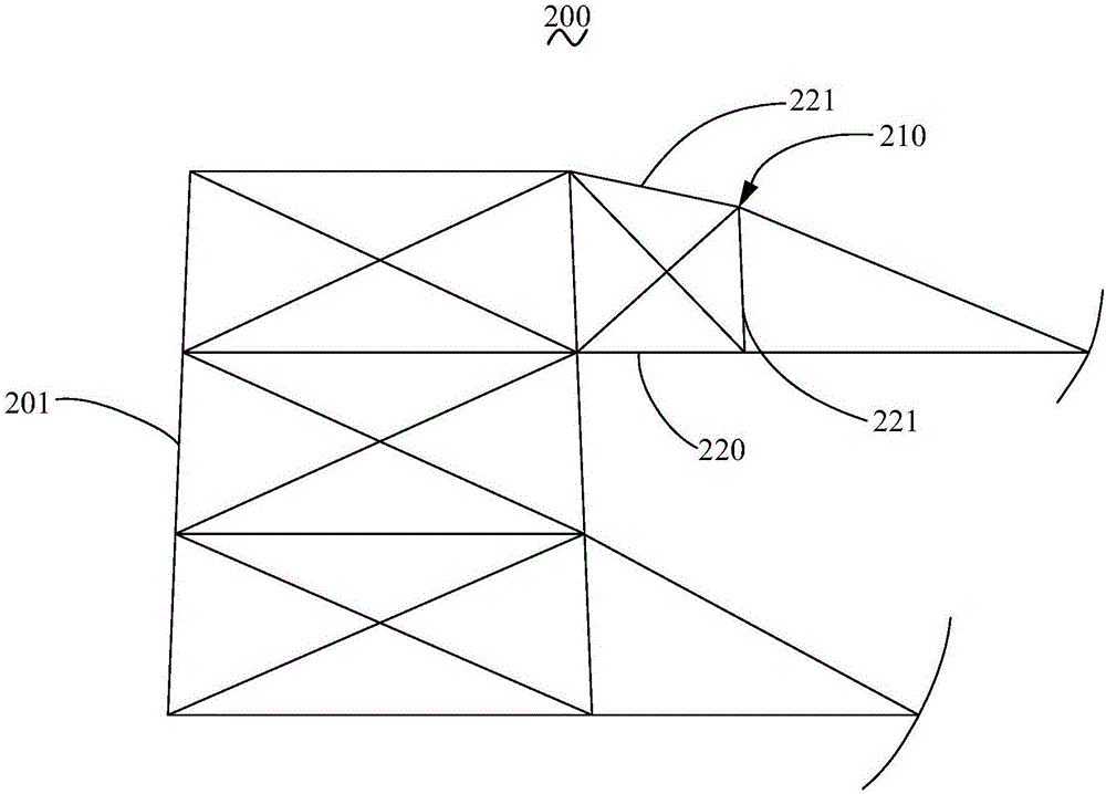
[0027] see image 3 It is a schematic plan view of the transmission tower 200 in the second embodiment of the present invention. The transmission tower 200 in the second embodiment is basically the same as the transmission tower 100 in the first embodiment. The cross-section is trapezoidal, its upper base is far away from the tower body 201, and its hypotenuse is on the upper side.
[0028] Specifically, the length of the column limb 221 away from the tower body 201 is shorter than the length of the metal bracket 210 connecting the tower body 201 , that is, the column limb 221 is the upper bottom of a trapezoid. The upper limb 221 of the metal bracket 210 serves as the hypotenuse of the trapezoid. In this way, the column limb 221 as the hypotenuse can disperse the force on the cross arm 210 , so that the mechanical properties of the cross arm 210 and the transmission tower 200 are good. The inclination angle of the column limb 221 as the hypotenuse can be controlled by adjus...
Embodiment 3
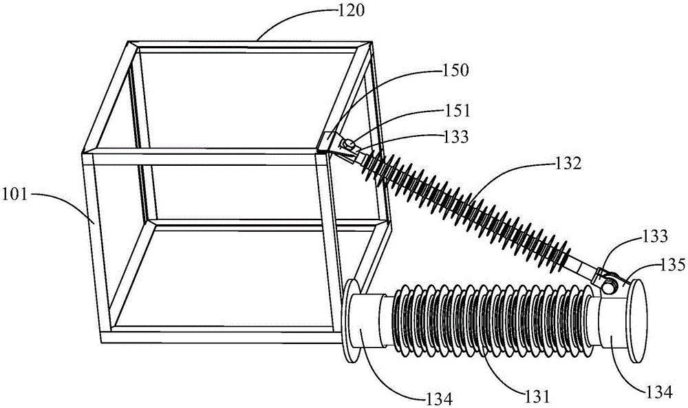
[0030] see Figure 4 The power transmission tower 300 in the third embodiment of the present invention is basically the same as the power transmission tower 100 in the first embodiment, except that the metal support 320 is provided with a cable-stayed member 336 along the axial direction of the cable-stayed insulator 332 . In this way, the cable-stayed part 336 and the cable-stayed insulator 332 can bear the oblique tension together, and the stress at the connection point between the cable-stayed insulator 332 and the metal bracket 320 can be improved.
[0031]Specifically, the cable-stayed piece 336 is made of metal materials such as angle steel, one end is connected to the apex of the metal bracket 320 for connecting the cable-stayed insulator 332 , and the other end is connected to the tower body 301 . In this embodiment, two cable-stayed members 336 are provided, corresponding to the two cable-stayed insulators 332 respectively. The cable stay 336 is connected with the to...
PUM
 Abstract
Description
Claims
Application Information
 - R&D
- Intellectual Property
- Life Sciences
- Materials
- Tech Scout
- Unparalleled Data Quality
- Higher Quality Content
- 60% Fewer Hallucinations
Browse by: Latest US Patents, China's latest patents, Technical Efficacy Thesaurus, Application Domain, Technology Topic, Popular Technical Reports.
© 2025 PatSnap. All rights reserved.Legal|Privacy policy|Modern Slavery Act Transparency Statement|Sitemap|About US| Contact US: help@patsnap.com