A main junction box support of an exdiic flameproof motor

A main junction box, explosion-proof technology, applied in the field of main junction box supports, can solve the problems of small space, inability to completely exchange motors, and inability to install the main junction box supports, etc., to achieve the effect of saving mold costs

Active Publication Date: 2016-09-14
上海电气集团上海电机厂有限公司
View PDF6 Cites 0 Cited by
  • Summary
  • Abstract
  • Description
  • Claims
  • Application Information

AI Technical Summary

Problems solved by technology

[0002] In the known technology, the main junction box support used for Exd II C flameproof motors, because of the large size of the connected main junction box, the main cable passing through the main junction box support is relatively thick, and it is necessary to adopt Flame-proof structure with spigot and external bolt installation method, so the size of the main junction box support and its upper and lower mounting surfaces need to be designed larger; but the axial ventilation channel on the cast iron frame of the Exd Ⅱ C flame-proof motor If the space at the location is narrow, the main junction box support of this structure cannot be installed on the air duct of the cast iron machine base; in this case, the cast iron machine base needs to be molded again, and the main junction box support is cast on the or change the entire cast iron frame into a steel plate welding frame, and weld the added steel plate main junction box support on the frame; therefore, the compact Exd Ⅱ C flameproof type of the cast iron frame The main junction box support cannot be installed on the axial ventilation channel of the cast iron frame, and the motors of the same type cannot be completely interchanged with motors of other explosion-proof grades in terms of appearance and installation dimensions.

Method used


Image

  • A main junction box support of an exdiic flameproof motor
  • A main junction box support of an exdiic flameproof motor
  • A main junction box support of an exdiic flameproof motor

Examples


Embodiment Construction

[0025] In order to better understand the technical solutions of the present invention, specific embodiments will be described in detail below in conjunction with the accompanying drawings.

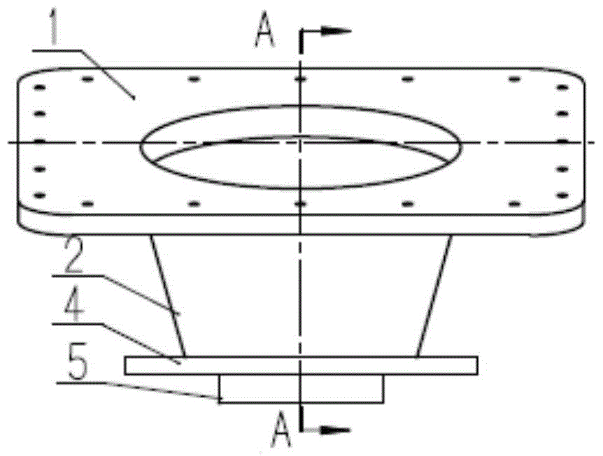
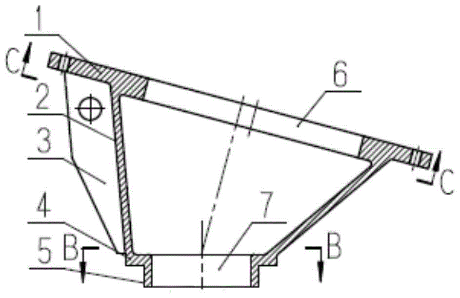
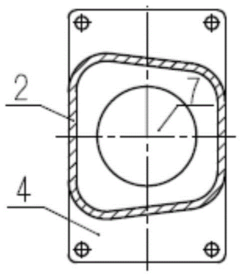
[0026] see Figure 1 to Figure 4 , an embodiment of the present invention, a main junction box support of an Exd II C flameproof motor adopts a shell structure, including a bottom mounting plane 4 , a top mounting plane 1 and a shell wall 2 .

[0027] The bottom installation plane 4 is arranged horizontally, the bottom installation plane 4 is rectangular, and the middle part of the bottom installation plane 4 is provided with a wire inlet 7, and the middle part of the bottom installation plane 4 is connected with a downward protruding circular outer stop 5, and the wire inlet The port 7 is set coaxially with the outer spigot 5; the top installation plane 1 is set obliquely and is located above the bottom installation plane 4, and the angle formed by the extension surface of the top install...


PUM


Abstract

The invention discloses a main junction box support for an ExdIIC type explosion-proof motor. The main junction box support for the ExdIIC type explosion-proof motor is of a shell structure and comprises a bottom installation plane, a top installation plane and a shell wall, wherein the bottom installation plane is arranged horizontally, the top installation plane is arranged obliquely and is located above the bottom installation plane, the included angle formed between the extension surface of the top installation plane and the extension surface of the bottom installation plane is an acute angle, the shell wall is in the shape of a barrel which is formed by four oblique planes, an opening in the upper end of the shell wall is larger than an opening in the lower end of the shell wall, the opening in the upper end of the shell wall is connected with the lower surface of the top installation plane, and the opening in the lower end of the shell wall is connected with the upper surface of the bottom installation plane. The main junction box support can be installed on an axial ventilation duct of a pig casting machine base of the ExdIIC type explosion-proof motor, and a die for the pig casting machine base can be used for motor bases on other explosive-proof grades.

Description

technical field [0001] The invention relates to a main junction box support of an Exd II C flameproof motor. Background technique [0002] In the known technology, the main junction box support used for Exd II C flameproof motors, because of the large size of the connected main junction box, the main cable passing through the main junction box support is relatively thick, and it is necessary to adopt Flame-proof structure with spigot and external bolt installation method, so the size of the main junction box support and its upper and lower mounting surfaces need to be designed larger; but the axial ventilation channel on the cast iron frame of the Exd Ⅱ C flame-proof motor If the space at the location is narrow, the main junction box support of this structure cannot be installed on the air duct of the cast iron machine base; in this case, the cast iron machine base needs to be molded again, and the main junction box support is cast on the or change the entire cast iron fram...

Claims


Application Information

Patent Timeline
Patent Type & Authority Patents(China)
IPC IPC(8): H02K5/22
CPCH02K5/136H02K5/225
Inventor 耿治起辛聪朱瑞霞初伟杰林荣来
Owner 上海电气集团上海电机厂有限公司
Why Eureka
Try Eureka