A cross-arm and corner tower

A corner tower, cross arm technology, applied in the direction of towers, building types, buildings, etc., can solve problems such as cross arms increasing the difficulty of production

Active Publication Date: 2018-10-02
SHANGHAI SHEMAR POWER ENG CO LTD
View PDF6 Cites 0 Cited by
  • Summary
  • Abstract
  • Description
  • Claims
  • Application Information

AI Technical Summary

Problems solved by technology

There is a minimum electrical clearance requirement between the wire and the corner tower 100. Generally, the distance between the wire and the corner tower 100 is increased by increasing the length of the cross arm to meet the electrical clearance requirement, but too long cross arms increase the production difficulty

Method used


Image

  • A cross-arm and corner tower
  • A cross-arm and corner tower
  • A cross-arm and corner tower

Examples


Embodiment 1

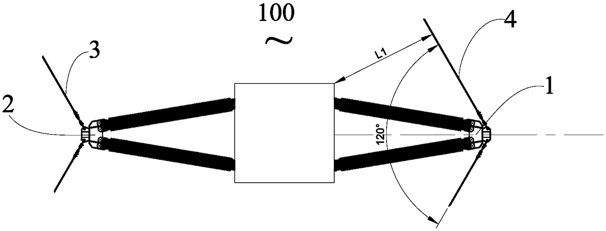
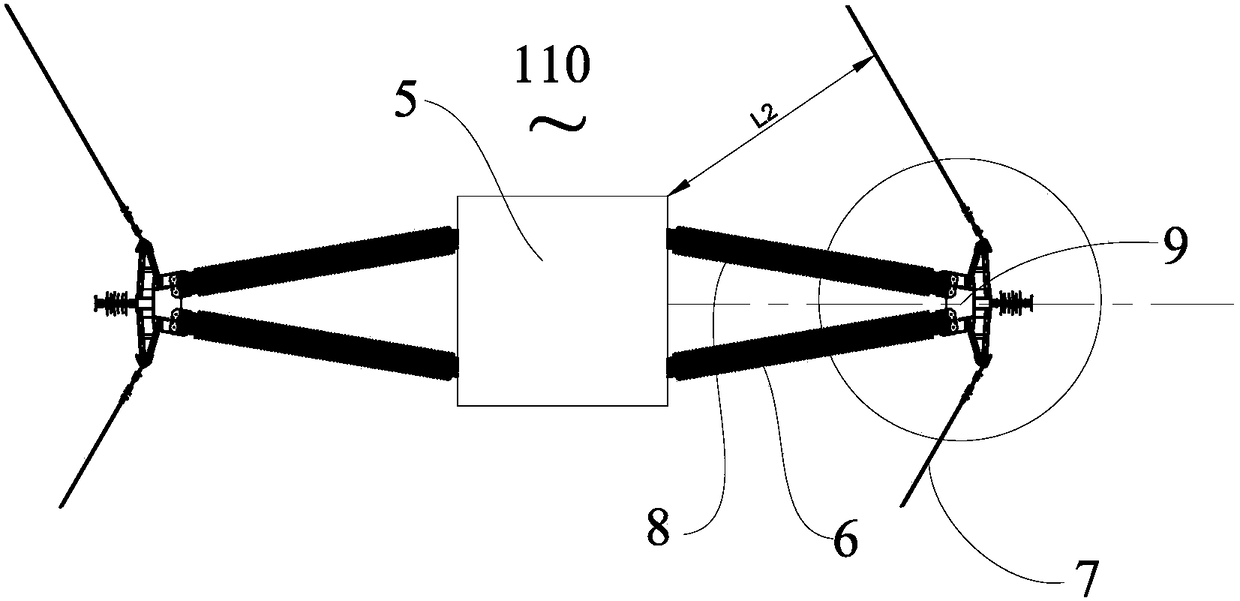
[0025] figure 2 Shown is a schematic diagram of the use of the corner tower 110 at the corner of the line. The corner tower 110 includes a tower body 5 and a cross arm 6 arranged on the tower body 5 , and the wires 7 at the corner are respectively hung on the cross arm 6 . In this embodiment, the turning angle of the wire 7 is 120°.

[0026] In this embodiment, the cross arm 6 is a V-shaped composite cross arm, the V-shaped open end is connected to the tower body 5 , and the apex is a free end for connecting the wire 7 . The cross-arm 6 includes two cross-arm insulators 8 and free ends, and the two cross-arm insulators 8 are fixed by end fittings 9 at the free ends.

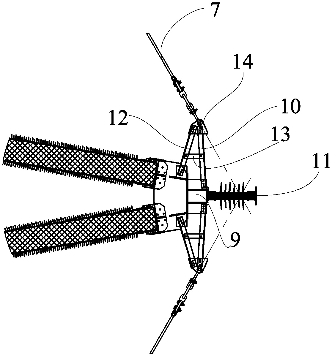
[0027] The partial enlarged picture of the free end of the cross arm is as follows: image 3 As shown, the free end of the cross arm includes an end fitting 9 , an extension piece 10 and a jumper device 11 . Specifically, extension pieces 10 are respectively provided on both sides of the end fitting 9 , one e...

Embodiment 2

[0036] Such as Figure 4 and Figure 5 As shown, in this embodiment, the extension piece 15 is fixed on the end fitting 16 as a whole, and the corner wires 17 are respectively connected to both ends of the extension piece 15 . Different from the first embodiment, the extension piece 15 of this embodiment is formed by connecting five brackets 18 with different lengths. The corresponding number of brackets can be selected according to the needs and assembled into an extension of the required length to meet the electrical clearance between the wire and the tower body. In addition, when the extension piece needs to be longer, it is more flexible to use multi-segment bracket assembly. In this implementation, a reinforcing piece and an auxiliary piece are also provided at the free end of the cross arm, and their function and structure are the same as those in Embodiment 1, and will not be repeated here.

Embodiment 3

[0038] The extension piece of the present invention does not limit its applied cross-arm structure, material, and wire transfer angle. Such as Figure 6 As shown, in the present embodiment, the cross arm 19 on the corner tower 120 is a straight cross arm, the wire 20 turns over at an angle of 100°, and the angle between the corner wire 20 and the center line of the cross arm 19 is 50°. In this embodiment, extension pieces are provided at both inner and outer corners.

[0039]Specifically, the cross arm 19 includes a cross arm insulator 21 and a free end away from the tower body 22 , and the free end includes an end fitting 23 and an extension piece 24 connected to the end fitting 23 . The extension piece 24 is a rectangular plate, its inclination angle in the vertical plane is 60°, and the two included angles with the center line of the cross arm 19 are respectively 70° and 110°. Since any angle between the extension piece 24 and the center line of the cross arm 19 is greate...


PUM


Abstract

The invention discloses a cross arm for an angle tower. The angle tower comprises a tower body, wherein one end of the cross arm is connected with the tower body, and one end, far from the tower body, is a free end and is used for being connected with a lead; the free end comprises an end part connecting component and an extension component, and the extension component is fixed with the end part connecting component and extends from the end part connecting component in a projection of a horizontal plane; and the lead is connected to the extension component, and an included angle between the extension component and the central line of the cross arm is larger than the included angle between the lead and the central line of the cross arm. By utilizing the extension component, the distance from the lead to the angle tower can be increased while a corner angle is met, the requirements of an electrical gap between the lead and the angle tower are met, and the cross arm does not need to be lengthened.

Description

technical field [0001] The invention relates to power transmission and transformation equipment, in particular to a cross arm and a corner tower. Background technique [0002] In the overhead transmission line, the transmission tower plays the role of supporting the wire. Specifically, the wire is supported by the cross arm fixed on the pole body of the transmission tower. The specific method is to hang the wire on the free end of the cross arm of the transmission tower. When the direction of the line needs to be changed, the transmission pole tower used to change the direction of the line is called a corner tower. [0003] Such as figure 1 As shown, the corner tower 100 has an outer corner 1 and an inner corner 2, the wire 3 at the inner corner 2 tends to be far away from the corner tower 100, and the wire 4 at the outer corner 1 tends to approach and then move away from the corner tower 100. There is a minimum electrical clearance requirement between the wire and the cor...

Claims


Application Information

Patent Timeline
Patent Type & Authority Patents(China)
IPC IPC(8): E04H12/24
CPCE04H12/24
Inventor 马斌邱勇郁杰李德权王青占王兵
Owner SHANGHAI SHEMAR POWER ENG CO LTD
Why Eureka
Try Eureka