Permanent magnet rotor

A technology of permanent magnets and rotors, applied in the field of rotors, can solve the problems of reduced yield, increased production cost, and impact on yield

Inactive Publication Date: 2013-07-24
广东正民高新磁电有限公司
View PDF4 Cites 0 Cited by
  • Summary
  • Abstract
  • Description
  • Claims
  • Application Information

AI Technical Summary

Problems solved by technology

[0002] The rotor has a coil structure and a permanent magnet structure. For a rotor with a permanent magnet, usually only one permanent magnet is sleeved on the rotor. However, when the axial length of the rotor increases, the magnet also needs to increase the axial length, but the increase in magnet processing The axial length will affect the yield, which will reduce the yield and increase the production cost

Method used


Image

  • Permanent magnet rotor
  • Permanent magnet rotor
  • Permanent magnet rotor

Examples


Embodiment Construction

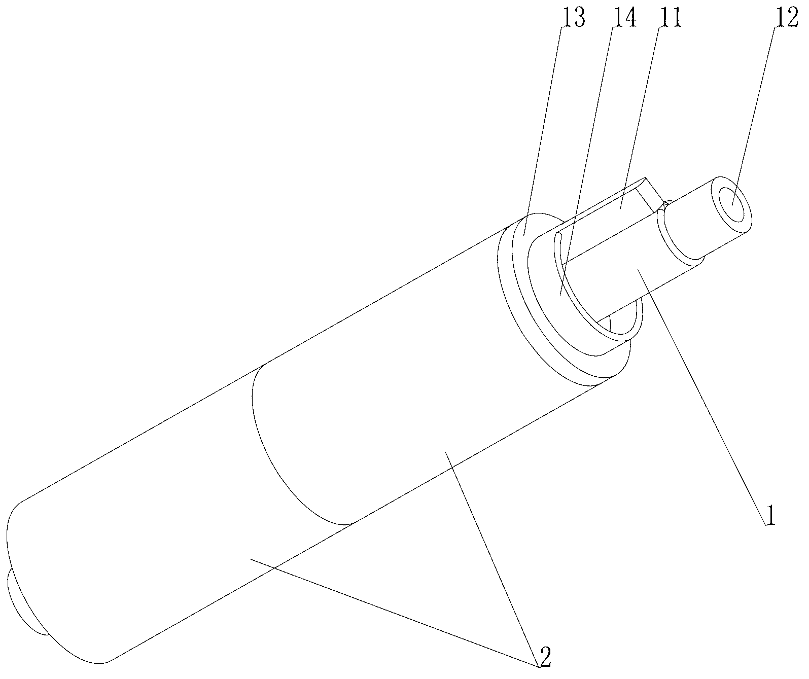
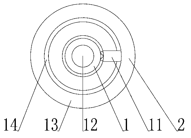
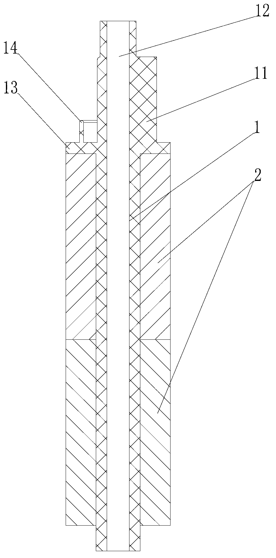
[0014] Such as figure 1 The rotor shown includes several cylindrical magnets 2 connected head to tail, a central hole is provided at the center of the magnets 2, and a rotating shaft 1 is arranged in the central hole of the magnets 2 to connect and fix each magnet 2 in series. The same magnetic poles on the magnets 2 are kept on the same side, and the fixing of the rotating shaft 1 can ensure that the magnetic repulsion between the magnets 2 will not cause the magnets to disengage or rotate. At least one end of the rotating shaft 1 protrudes from the magnet 2 and is placed outside as a transmission shaft for connecting external devices. There is also a rotating key 11 at the end of the rotating shaft 1 placed outside the magnet 2, and a stopper is also provided on the rotating shaft 1 at the end of the rotating key 11. 13. The baffle 13 seals one end of the magnet. The baffle 13 is also provided with a ring-shaped rib 14 which can act as a buffer. There is also a through hole ...


PUM


Abstract

The invention discloses a permanent magnet rotor, which is characterized by comprising a plurality of magnets (2) which are successively connected with one other in a head-to-tail manner, and the same magnetic poles of the magnets (2) are located at a same side; the magnets (2) are cylindrical and provided with central holes at the center; a rotating shaft (1) for fixing the magnets (2) is fixed at the central holes; at least one end of the rotating shaft (1) is arranged outside the magnets (2); a rotating key (11) fixed on the rotating shaft (1) is arranged at the end, outside the magnets (2), of the rotating shaft (1); the rotating shaft (1) is subjected to injection molding in the central holes of the magnets (2) and made of metal; a through hole (12) is formed in the center of the rotating shaft (1), and a stop piece (13) sealing one end of the magnet (2) is also arranged at the side, close to the rotating key (11), of the rotating shaft (1); and an annular convex edge (14) is formed on the stop piece (13).

Description

【Technical field】 [0001] The invention relates to rotors, in particular rotors provided with permanent magnets. 【Background technique】 [0002] The rotor has a coil structure and a permanent magnet structure. For a rotor with a permanent magnet, usually only one permanent magnet is sleeved on the rotor. However, when the axial length of the rotor increases, the magnet also needs to increase the axial length, but the increase in magnet processing The axial length will affect the yield, reduce the yield and increase the production cost. 【Content of invention】 [0003] In order to solve the deficiencies in the prior art, an axially long rotor with a simple structure is provided. [0004] The technical scheme adopted in the present invention is: [0005] A permanent magnet rotor, comprising a number of magnets connected end to end in sequence and with the same magnetic poles on the same side, each of the magnets is cylindrical and has a center hole in the center, and a rotat...

Claims


Application Information

Patent Timeline
IPC IPC(8): H02K1/27
Inventor 孙澄清
Owner 广东正民高新磁电有限公司
Why Eureka
Try Eureka