Panoramic video splicing method

A technology for panoramic video and splicing images, applied in the field of panoramic video splicing, can solve problems such as unsatisfactory splicing effect, achieve ideal splicing effect, good image quality, and meet the needs of use.

Inactive Publication Date: 2016-10-26
CHINA SOUTHERN POWER GRID COMPANY
View PDF3 Cites 22 Cited by
  • Summary
  • Abstract
  • Description
  • Claims
  • Application Information

AI Technical Summary

Problems solved by technology

The existing panoramic video stitching technology is affected by factors such as changes in shooting scenes and different shooting angles, and the stitching effect is not very ideal

Method used


Image

  • Panoramic video splicing method
  • Panoramic video splicing method
  • Panoramic video splicing method

Examples


Embodiment 1

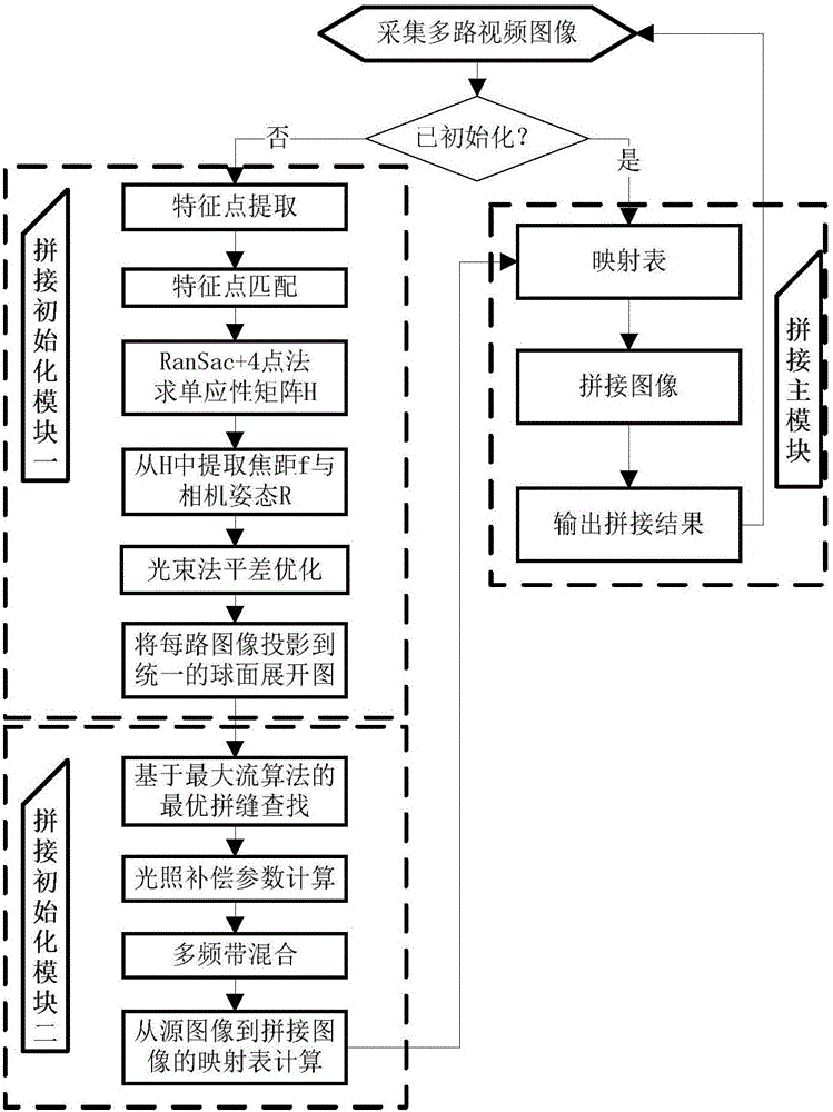
[0057] Embodiment 1: as figure 1 As shown, the panorama stitching algorithm is divided into initial stitching and main stitching. Initial stitching generates a mapping table from the source image to the stitched image, and the main stitching directly projects the multi-channel video images participating in stitching to the final panoramic image according to the mapping table, and outputs After stitching the results, the panorama stitching of the next frame is performed.

[0058] The task of initialization stitching is to generate this very critical mapping table. According to the characteristics of each module, it is further divided into initialization stitching 1 and initialization stitching 2. Initial stitching 1 is estimated to get a set of Motion parameters. This group of motion parameters specifically includes the focal length f of each camera and the attitude matrix R of the camera. Through the focal length f of the camera and the attitude matrix R of the camera, the ori...


PUM


Abstract

The invention discloses a panoramic video splicing method. A mapping table from the source image to the splicing image is generated by means of 'initial splicing', the multi-channel video images that participate in the splicing are directly projected to the final panoramic image by means of 'main splicing' based on the mapping table, and the splicing result is output. The spliced panoramic video image has the advantages of good quality and ideal splicing effect, and can meet the various demands of consumers.

Description

technical field [0001] The invention relates to a video splicing method, in particular to a panoramic video splicing method. Background technique [0002] Panoramic video is the stitching of multiple channels of camera video into a video with a larger equivalent field of view. Traditionally, when the equivalent field of view is 360 degrees, it is called "panorama", but at present, the concept of panorama can be used if it exceeds 180 degrees. The existing panoramic video stitching technology is affected by factors such as changes in shooting scenes and different shooting angles, and the stitching effect is not very ideal. Contents of the invention [0003] The technical problem to be solved by the present invention is to provide a panoramic video splicing method, which is not affected by changes in the shooting scene and shooting angle factors, and has good imaging quality and ideal splicing effect. [0004] In order to solve the problems of the technologies described ab...

Claims


Application Information

Patent Timeline
Patent Type & Authority Applications(China)
IPC IPC(8): G06T3/40
CPCG06T3/4038
Inventor 李金陶文伟张喜铭樊腾飞梁寿愚方文崇高红亮
Owner CHINA SOUTHERN POWER GRID COMPANY
Why Eureka
Try Eureka