A loopback detection method, bbu, rru and optical access network system
A loopback detection and network system technology, applied in the field of optical communication, can solve the problems of long time and high labor cost
- Summary
- Abstract
- Description
- Claims
- Application Information
AI Technical Summary
Problems solved by technology
Method used
Image

Examples
Embodiment 1
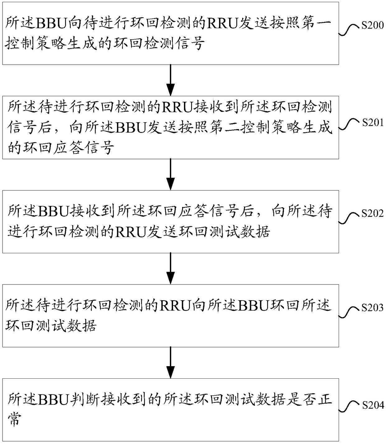
[0142] As shown in Figure 2(a), this embodiment provides a loopback detection method, which is applied to an optical access network system including a baseband processing unit BBU and at least one remote radio unit RRU, including the following steps:
[0143] Step S200, the BBU sends a loopback detection signal generated according to the first control strategy to the RRU to be loopback detection;
[0144] Step S201, after receiving the loopback detection signal, the RRU to be subjected to loopback detection sends a loopback response signal generated according to the second control strategy to the BBU;
[0145] Step S202, after the BBU receives the loopback response signal, it sends loopback test data to the RRU to be tested for loopback;
[0146] Step S203, the RRU to be subjected to loopback detection loops back the loopback test data to the BBU;
[0147] Step S204, the BBU judges whether the received loopback test data is normal.
[0148] As shown in Figure 2(b), after the...
Embodiment 2
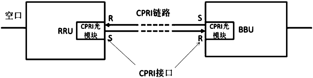
[0176] Such as Figure 4 As shown, this embodiment provides an optical access network system, which is characterized in that it includes a baseband processing unit BBU and at least one remote radio unit RRU;
[0177] The BBU is configured to send a loopback detection signal generated according to the first control strategy to the RRU in the system to be subjected to loopback detection; the synchronization state judgment end of the BBU receives the loopback detection signal to be performed After the loopback response signal sent by the RRU, send loopback test data to the RRU to be detected for loopback; judge whether the loopback test data of the RRU loopback for loopback detection to be detected is normal;
[0178] The RRU to be subjected to loopback detection is used to send the loopback detection signal generated according to the second control strategy to the BBU after the synchronous state judgment end of the RRU to be subjected to loopback detection receives the loopback ...
Embodiment 3
[0204] As shown in FIG. 7(a), this embodiment provides a loopback detection method, which is applied to a baseband processing unit BBU, and includes the following steps:
[0205] Step S700, sending a loopback detection signal generated according to the first control strategy to the RRU to be subjected to loopback detection;
[0206] Step S701, after determining that the loopback response signal sent by the RRU to be tested for loopback is received, send loopback test data to the RRU to be tested for loopback; wherein the loopback response signal is the a signal generated by the RRU according to the second control strategy;
[0207] Step S702, judging whether the received loopback test data is normal.
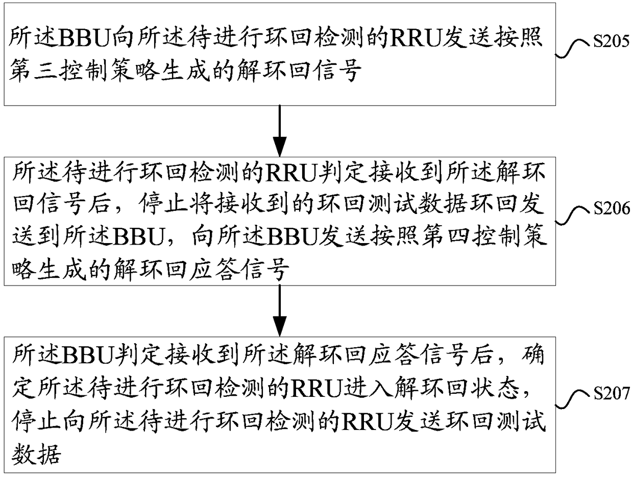
[0208] Optionally, as shown in Figure 7(b), the method may also include:
[0209] Step S703, sending a de-loopback signal generated according to the third control strategy to the RRU to be subjected to loopback detection;
[0210] Step S704, after determining that the de-loop...
PUM
 Abstract
Description
Claims
Application Information
 - R&D
- Intellectual Property
- Life Sciences
- Materials
- Tech Scout
- Unparalleled Data Quality
- Higher Quality Content
- 60% Fewer Hallucinations
Browse by: Latest US Patents, China's latest patents, Technical Efficacy Thesaurus, Application Domain, Technology Topic, Popular Technical Reports.
© 2025 PatSnap. All rights reserved.Legal|Privacy policy|Modern Slavery Act Transparency Statement|Sitemap|About US| Contact US: help@patsnap.com