Internal mixer rotor

A technology of internal mixer and rotor, which is applied in the field of continuous internal mixer rotor, which can solve the problems of limited material stability, small feeding volume, and low production capacity, and achieve the effect of large feeding volume, good stability, and good dispersion

Inactive Publication Date: 2018-06-12
NANJING YONGTENG CHEM EQUIP
View PDF9 Cites 0 Cited by
  • Summary
  • Abstract
  • Description
  • Claims
  • Application Information

AI Technical Summary

Problems solved by technology

[0002] The conventional rotor includes a conveying section and a threaded section. The single-lead screw groove of the conveying section is deep, and the flute angle of the threaded section is large. The stability of the conveyed material is limited, the feeding volume is small, and the production capacity is low. It is especially not suitable for expansion. Loose material transportation and other issues

Method used


Image

  • Internal mixer rotor
  • Internal mixer rotor

Examples


Embodiment 1

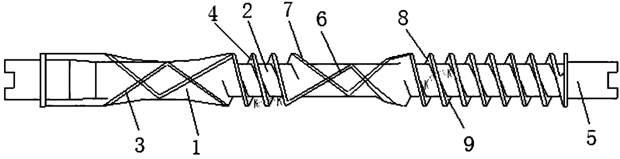
[0015] Such as Figure 1~Figure 2 As shown, the internal mixer rotor is characterized in that it includes a rotor shaft 5, and the rotor shaft 5 is provided with a conveying section 1 and a threaded section 2, and the conveying section 1 is provided with a double-lead screw groove 3, and the The slope angle of the flute angle 4 of the thread segment 2 is 3-30°.

[0016] The double-lead screw groove 3 includes a first screw groove 6 and a second screw groove 7, both of which are S-shaped and intersect each other.

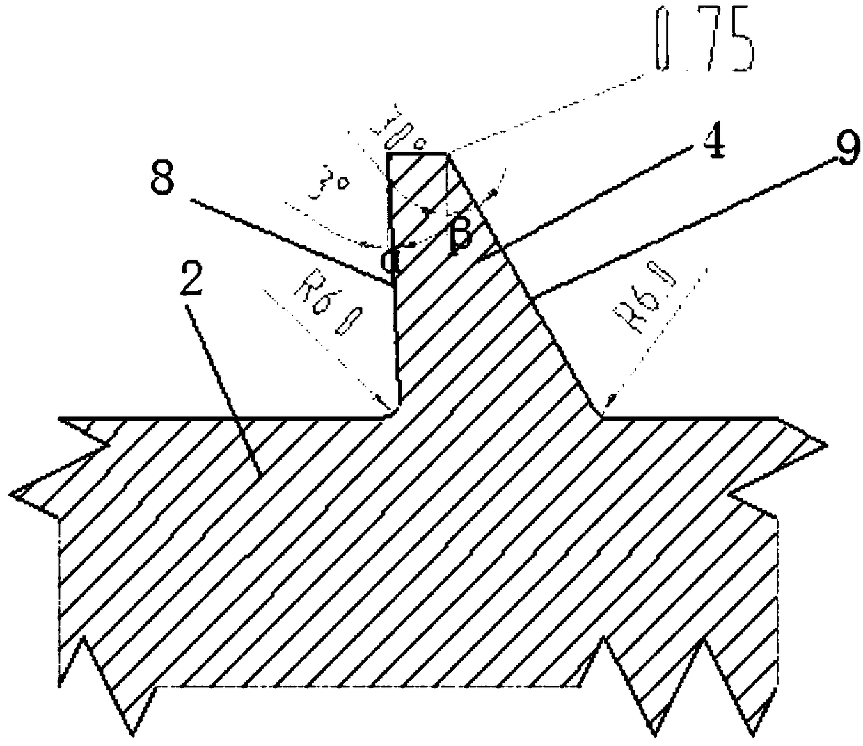
[0017] The flute angle 4 includes a first inclined plane 8 facing the feeding direction and a second inclined plane 9 facing the discharging direction, and the top ends of the first inclined plane 8 and the second inclined plane 9 extend obliquely towards the feeding direction, so The inclination angle α of the first slope 8 is smaller than the slope angle β of the second slope 9 .

[0018] The inclination angle α of the first inclined surface 8 is 3°, and the incl...

Embodiment 2

[0020] Such as Figure 1~Figure 2 As shown, the internal mixer rotor is characterized in that it includes a rotor shaft 5, and the rotor shaft 5 is provided with a conveying section 1 and a threaded section 2, and the conveying section 1 is provided with a double-lead screw groove 3, and the The slope angle of the flute angle 4 of the thread segment 2 is 3-30°.

[0021] The double-lead screw groove 3 includes a first screw groove 6 and a second screw groove 7, both of which are S-shaped and intersect each other.

[0022] The flute angle 4 includes a first inclined plane 8 facing the feeding direction and a second inclined plane 9 facing the discharging direction, and the top ends of the first inclined plane 8 and the second inclined plane 9 extend obliquely towards the feeding direction, so The inclination angle α of the first slope 8 is smaller than the slope angle β of the second slope 9 .

[0023] The inclination angle α of the first inclined surface 8 is 8°, and the incl...


PUM


Abstract

The invention discloses a rotor of an internal mixer. The rotor of the internal mixer is characterized by comprising a rotor shaft (5), wherein a conveying section (1) and a thread section (2) are arranged on the rotor shaft (5), a double-lead screw channel (3) is arranged on the conveying section (1), the inclination angles of the slopes of each screw flight corner (4) of the thread section (2) is 3-30 degrees, each screw flight corner (4) comprises a first slope (8) right opposite to the feeding direction and a second slope (9) right opposite to the discharging direction, the top end of each first slope (8) and the top end of each second slope (9) both extend towards the feeding direction in an inclined manner, and the inclination angle alpha of each first slope (8) is smaller than the inclination angle beta of the corresponding second slope (9). The rotor of the internal mixer is simple in structure, capable of stably conveying bulky materials, large in feeding quantity, good in dispersion effect and capable of improving the yield by 50%.

Description

technical field [0001] The invention relates to a rotor of an internal mixer, in particular to a rotor of a continuous internal mixer mainly improved for filling bulky materials. Background technique [0002] The conventional rotor includes a conveying section and a threaded section. The single-lead screw groove of the conveying section is deep, and the flute angle of the threaded section is large. The stability of the conveyed material is limited, the feeding volume is small, and the production capacity is low. It is especially not suitable for expansion. Transportation of loose materials and other issues. Contents of the invention [0003] The technical problem to be solved by the present invention is to provide an internal mixer rotor with simple structure, stable transportation of bulky materials, large feeding volume, good dispersion effect and 50% increase in output. [0004] In order to solve the problems of the technologies described above, the technical solution ...

Claims


Application Information

Patent Timeline
Patent Type & Authority Patents(China)
IPC IPC(8): B29B7/22
CPCB29B7/22B29B7/183B29B7/186
Inventor 舒作欢向远亮
Owner NANJING YONGTENG CHEM EQUIP
Why Eureka
Try Eureka