
Vehicle window glass breaking escaping device

A technology of car window glass and escape device, applied in the field of escape device, can solve the problems of delayed escape timing, easy loss, and inability to function, and achieves the effect of fast response speed

Inactive Publication Date: 2016-11-09
孔令斐 +1
View PDF5 Cites 3 Cited by
  • Summary
  • Abstract
  • Description
  • Claims
  • Application Information

AI Technical Summary

Problems solved by technology

[0003] The current window glass breaking devices are mostly emergency hammers, which have many shortcomings in emergency use: ① After an accident, the window breaking behavior is operated by passengers themselves, and passengers are not familiar with the location and operation of the emergency hammer , and cannot be operated quickly and in a timely manner; ②Existing car window glass is usually relatively strong, while the emergency hammer is manually operated, requiring high strength and operating space requirements, and it is difficult to break the car window, and it often takes multiple times to break the window Successful; ③ Since the emergency hammer needs to be operated by hand, it is usually temporarily fixed near the car window, which is easy to lose and cannot function when an accident occurs
To sum up, the existing emergency hammer has many defects and poor reliability. After an accident, it cannot be used to break windows in time, which delays the best time to escape.

Method used


Image

  • Vehicle window glass breaking escaping device
  • Vehicle window glass breaking escaping device

Examples


Embodiment Construction

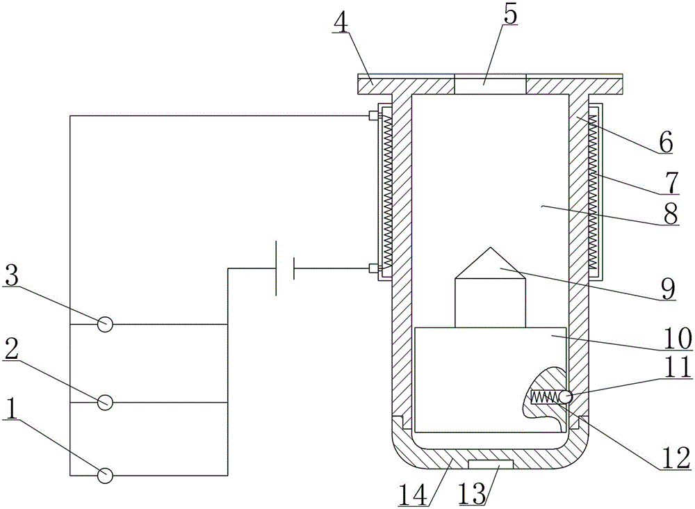
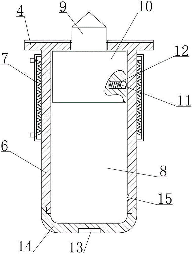
[0013] Such as figure 1 , 2 As shown, a broken escape device for vehicle window disclosed by the present invention includes a housing 6, the housing 6 is preferably cylindrical, the housing 6 is provided with a column chamber 8, and the column chamber 8 is provided with a Sliding sliding bolt 10; the sliding bolt 10 is made of a metal material that can be attracted by a magnet, and a blind hole is opened on its side wall, and a spring 12 and a positioning touch bead 11 are arranged in the blind hole; and the rear part of the column chamber 8 Then be provided with a positioning groove 15 on the side wall, the initial position of slide bolt 10 is limited by positioning touch bead 11 and positioning groove 15 and is positioned at the rear end of column cavity 8, promptly slide bolt 10 is always in initial position when no accident occurs, and Keep the state to be activated; the front end of the sliding bolt 10 is provided with a bump pin 9 for hitting the window glass, and the f...


PUM


Abstract

The invention discloses a vehicle window glass breaking escaping device. A column cavity is formed in a shell of the vehicle window glass breaking escaping device and internally provided with a sliding bolt. The sliding bolt is made of a metal material capable of being attracted by a magnet, and the initial position of the sliding bolt is located at the rear end of the column cavity. A hitting pin is arranged at the front end of the sliding bolt. An electromagnetic coil is arranged on the outer side of the front portion of the shell, conduction of a working circuit of the electromagnetic coil can be triggered through switches at three positions, the first switch is a temperature induction automatic switch, the second switch is a manual switch installed in a cab, and the third switch is an emergency trigger switch. An annular base is connected to the front end of the shell. The front end face of the annular base can be bonded to vehicle window glass, so that the whole device is fixed. A via hole allowing the hitting pin to penetrate is formed in the middle portion of the annular base. Electromagnetic drive is adopted in the vehicle window glass breaking escaping device, one-key operation is conducted, the response speed is high, and the window breaking success probability is high. An automatic window breaking manner is adopted in the vehicle window glass breaking escaping device, multiple triggering manners are provided, the vehicle window glass can be broken as soon as possible after an accident happens, and the optimal escaping opportunity can be earned for passengers.

Description

technical field [0001] The invention relates to an escape device, in particular to an escape device for broken window glass. Background technique [0002] With the rapid development of society, people travel more and more frequently in their life and work, among which buses, trains and subways are the most commonly used means of transportation. In order to ensure the safety of driving and the comfort of the internal environment, this type of transportation generally adopts a closed compartment, that is, the window glass is usually not openable. When the vehicle encounters an emergency such as a fire, the doors and escape doors are crowded or even cannot be opened normally. If the window glass can be quickly removed, it will become the best escape route, so it is of great significance to develop a highly reliable window glass breaking escape device. [0003] The current window glass breaking devices are mostly emergency hammers, which have many shortcomings in emergency use:...

Claims


Application Information

Patent Timeline
Patent Type & Authority Applications(China)
IPC IPC(8): B60R21/02
Inventor 孔令斐孔祥海
Owner 孔令斐
Learn More