
A motor rotary switch

A rotary switch and rotary shaft technology, applied in electrical switches, circuits, electrical components, etc., can solve the problems of reduced electrical safety, many components, complicated wiring, etc., and achieve the effect of simple wiring, few components, and high electrical safety.

Active Publication Date: 2018-02-23
江门市江海区柏健电器制造有限公司
View PDF8 Cites 0 Cited by
  • Summary
  • Abstract
  • Description
  • Claims
  • Application Information

AI Technical Summary

Problems solved by technology

[0002] Household appliances such as: mixers, meat grinders, juicers, etc. will be equipped with motor rotary switches. The existing motor rotary switches only have the function of rotating and shifting, and have no jog function. Household appliances such as mixers, meat grinders, and juicers are in use. When the jog function is usually used, it is necessary to add a jog switch, resulting in complicated wiring, many original parts, and reduced electrical safety.

Method used


Image

  • A motor rotary switch
  • A motor rotary switch
  • A motor rotary switch

Examples


Embodiment Construction

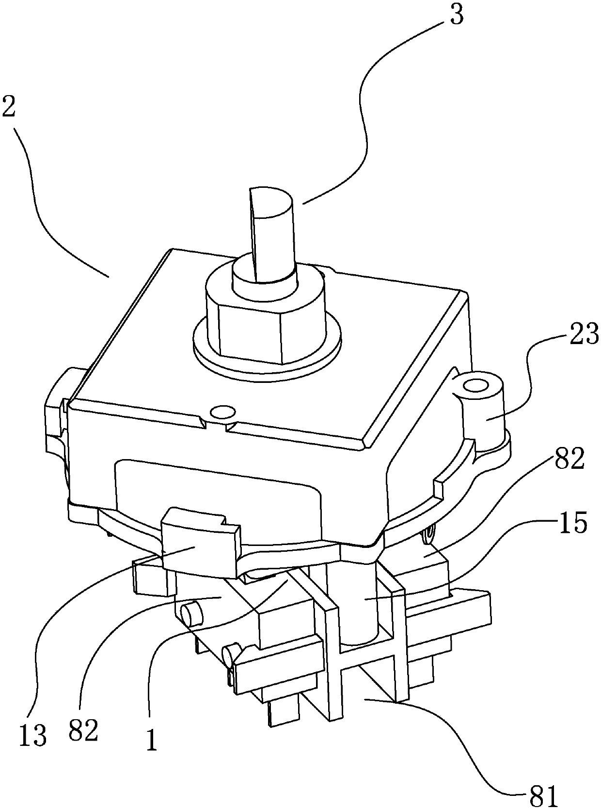
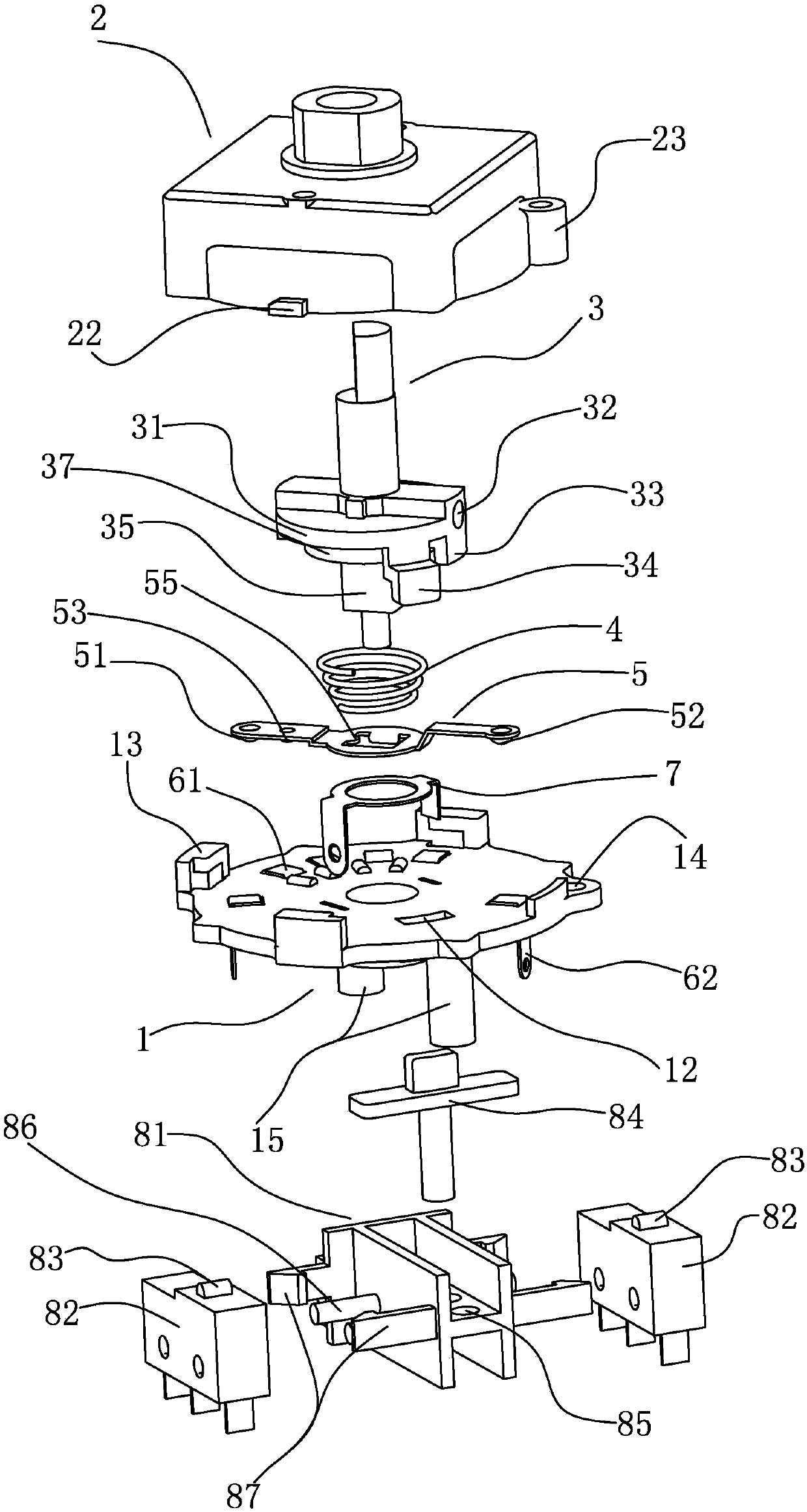
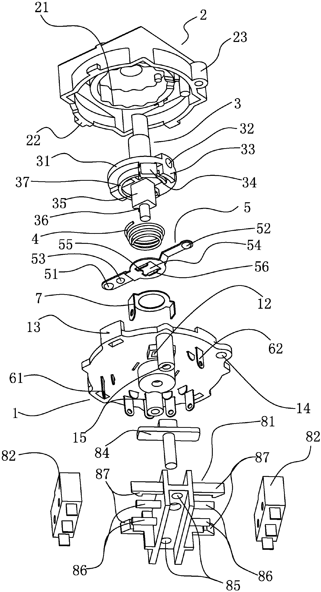
[0028] refer to Figure 1~3 , a motor rotary switch, including a chassis 1, a top cover 2 fixed on the chassis 1, a rotating shaft 3 rotatably arranged in the top cover 2 and / or chassis 1, and a rotation for positioning the rotation of the rotating shaft 3 Positioning device, the rotating shaft 3 is sequentially set with a switch spring 4 and a moving contact piece 5, the switching spring 4 and the moving contact piece 5 are in conflict, the chassis 1 is provided with more than one static contact piece, and the moving contact piece 5 is driven by the rotating shaft 3 Rotate and contact with each static contact respectively, the movable contact 5 is electrically connected with the central contact 7, the movable contact 5 includes a rotary contact 51 and a jogging contact 52, and the static contact includes a contact with the rotary contact 51 respectively. The rotary contact piece 61 and the jog contact piece 62 arranged with the jog contact 52, the bottom of the rotary contact...


PUM


Abstract

The present invention relates to the field of a wiring switch, and discloses a motor rotary switch. When shifts are needed to rotate, a rotary shaft is rotated to drive a moving contact piece sleeving the rotary shaft. A rotary positioning device positions the rotation of the rotary shaft and the moving contact piece. A rotary contact is successively touched with rotary contact pieces on a base plate, and thus the electric connection and the shift adjustment are realized. When the point control is needed to be performed, a point moving contact is only needed to be rotated a point moving contact pieces, and then the point electric connection of the point moving contact and the point moving contact pieces is realized by pressing the rotary shaft. A micro-moving contact point on a micro-moving switch is pressed by pressing the rotary shaft, and the micro-moving switch is touched to carry out motions. The motor rotary switch has simple wirings, few elements, and high electric appliance safety.

Description

technical field [0001] The invention relates to the field of wiring switches, in particular to a motor rotary switch. Background technique [0002] Household appliances such as: mixers, meat grinders, juicers, etc. will be equipped with motor rotary switches. The existing motor rotary switches only have the function of rotating and shifting, and have no jogging function. Household appliances such as mixers, meat grinders, and juicers are in use. The inching function is usually used when the switch is used, and an additional inching switch needs to be added, resulting in complicated wiring, many originals, and reduced electrical safety. Contents of the invention [0003] In order to overcome the deficiencies of the prior art, the present invention provides a motor rotary switch, which has the functions of rotary gear shifting and jogging, simple wiring, few components, and high electrical safety. [0004] The technical solution adopted by the present invention to solve its...

Claims


Application Information

Patent Timeline
Patent Type & Authority Patents(China)
IPC IPC(8): H01H25/06
CPCH01H25/06
Inventor 余柏亮
Owner 江门市江海区柏健电器制造有限公司
Learn More