a high frequency relay

A relay and high-response technology, applied in the field of high-response relays, can solve the problems of low response frequency, poor elasticity, fatigue cracks, etc., and achieve the effect of high response frequency and fast speed

Active Publication Date: 2018-02-06
SHANXI DATANG INTERNATIONAL LINFEN THERMAL POWER CO LTD
View PDF3 Cites 0 Cited by
  • Summary
  • Abstract
  • Description
  • Claims
  • Application Information

AI Technical Summary

Problems solved by technology

The traditional relay uses an elastic copper sheet as the moving contact, which has poor elasticity and is prone to fatigue cracks after repeated use, which affects its service life. At the same time, its response frequency is not high, so a new type with high frequency response is urgently needed. relay

Method used


Image

  • a high frequency relay
  • a high frequency relay
  • a high frequency relay

Examples


Embodiment

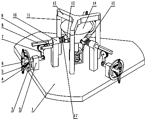
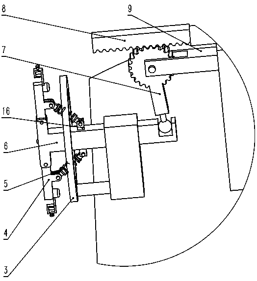
[0015] like figure 1 , figure 2 , image 3 , Figure 4 , Figure 5 As shown, a high-frequency response relay includes a base plate 1, three uprights 11, a triangular support 12, a tapered slider 14, a push-pull electromagnet 15, and three contact units, characterized in that: the three uprights 11 It is installed vertically above the bottom plate 1, and a triangular bracket 12 is installed above the column 11. There is a vertical downward cylindrical shaft in the center of the triangular bracket 12, and the tapered slider 14 has a circular hole in the center and passes through the This round hole is installed on the cylindrical shaft, the small end of the conical slider is at the bottom, and the big end is at the top. The conical slider 14 can slide up and down. The sliding of the conical slider is controlled by the push-pull electromagnet 15. The shell is fixed on the bottom plate 1, and the armature of the push-pull electromagnet 15 is connected to the bottom of the con...


PUM


Abstract

The invention provides a high frequency response relay, which comprises a base plate, three upright columns, a triangular frame, a tapered sliding block, a push-pull electromagnet and three contact unit, and is characterized in that the three upright columns are vertically installed on the base plate, the triangular frame is installed on the upright columns, the center of the triangular frame is provided with a vertical downward cylindrical shaft, the center of the tapered sliding block is provided with a circular hole, the tapered sliding block is installed on the cylindrical shaft through the circular hole, the small end of the tapered sliding block is arranged on the top, the big end of the tapered sliding block is arranged at the bottom, and the tapered sliding block can slide up and down. According to the invention, on-off of a main circuit is controlled through the push-pull electromagnet, the high frequency response relay enables a contact to be higher in contact speed by being matched with a gear-rack speed amplifying mechanism, and the response frequency is higher.

Description

technical field [0001] The invention relates to the technical field of relays, in particular to a high-frequency response relay. Background technique [0002] A relay is an electrical control device, which is an electrical appliance that makes a predetermined step change in the controlled quantity in the electrical output circuit when the change of the input quantity (excitation quantity) reaches the specified requirements. It has an interactive relationship between the control system (also known as the input loop) and the controlled system (also known as the output loop). Usually used in automatic control circuits, it is actually an "automatic switch" that uses small current to control the operation of large current, so it plays the role of automatic adjustment, safety protection, and conversion circuit in the circuit. The traditional relay uses an elastic copper sheet as the moving contact, which has poor elasticity and is prone to fatigue cracks after repeated use, which...

Claims


Application Information

Patent Timeline
Patent Type & Authority Patents(China)
IPC IPC(8): H01H53/01
CPCH01H53/01
Inventor 王鹏孟庆文韩志胜李红玥姚宏业王红兵程钰
Owner SHANXI DATANG INTERNATIONAL LINFEN THERMAL POWER CO LTD
Why Eureka
Try Eureka