Nozzle structure for injection blowing

A technology of pressing plate and hot runner plate is applied in the field of injection blowing machine, which can solve the problems of easy material blocking of the injection nozzle, no temperature control of the injection nozzle, and difficulty in producing products, etc., and achieves the effect of solving the problem of temperature control and material blocking.

Inactive Publication Date: 2016-11-16
JIANGSU VICTORY MACHINERY
View PDF5 Cites 0 Cited by
  • Summary
  • Abstract
  • Description
  • Claims
  • Application Information

AI Technical Summary

Problems solved by technology

With this conventional structure, the nozzle is directly in contact with the injection mold cavity, and the nozzle is not temperature controlled, which makes the nozzle easy to block, and the temperature at the bottom of the injection molded tube is difficult to control, resulting in uneven thickness at the bottom of the product, making it difficult to produce qualified products. The product

Method used


Image

  • Nozzle structure for injection blowing

Examples


Embodiment Construction

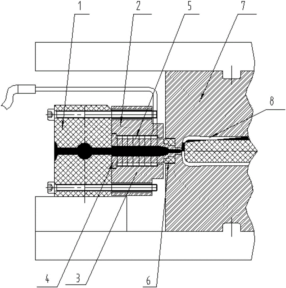
[0010] Specific embodiments of the present invention will be described in detail below in conjunction with the accompanying drawings.

[0011] Such as figure 1 As shown, a nozzle structure for injection and blowing includes a hot runner plate 1 arranged on a runner backing plate, and a nozzle pressure plate connected to the hot runner plate 1 . The nozzle pressure plate includes an upper pressure plate 2 and a lower pressure plate 3, and the upper pressure plate 2 and the lower pressure plate 3 are respectively connected with the hot runner plate 1 through connecting bolts. Nozzle 4 is set in the nozzle pressure plate, and the outer periphery of the nozzle 4 is provided with a heating device 5, and the discharge end of the nozzle 4 is provided with a PEEK heat insulation pad 6, and the discharge end of the nozzle 4 extends into the molding In the injection molding cavity of the mold 7, a molding mandrel 8 is provided in the injection molding cavity.

[0012] The above-mentio...


PUM


Abstract

The invention discloses a nozzle structure for injection blowing. The nozzle structure comprises a hot-runner plate and a nozzle pressing plate, wherein the hot-runner plate is arranged on a runner backing plate, the nozzle pressing plate is connected with the hot-runner plate, a nozzle is arranged in the nozzle pressing plate, a heating device sleeves the periphery of the nozzle, an insulation pad sleeves the discharge end of the nozzle, the discharge end of the nozzle extends into an injection molding cavity of a forming die, and a forming core rod is arranged in the injection molding cavity. By using the nozzle structure for injection blowing, the temperature of the bottom of a pipe blank is easy to control.

Description

technical field [0001] The invention relates to an injection blowing machine, in particular to a nozzle structure for injection blowing. Background technique [0002] Conventional injection and blowing nozzles include a hot runner plate arranged on the runner backing plate, and a nozzle pressure plate connected to the hot runner plate. A nozzle is arranged in the nozzle pressure plate, and the discharge end of the nozzle extends into the injection mold of the molding mold. In the mold cavity, a molding mandrel is arranged in the injection mold cavity. With this conventional structure, the nozzle is directly in contact with the injection mold cavity, and the nozzle is not temperature controlled, which makes the nozzle easy to block, and the temperature at the bottom of the injection molded tube is difficult to control, resulting in uneven thickness at the bottom of the product, making it difficult to produce qualified products. The product. Contents of the invention [00...

Claims


Application Information

Patent Timeline
IPC IPC(8): B29C45/27B29C45/73
CPCB29C45/2737B29C45/278
Inventor 刁增钱伟孟博
Owner JIANGSU VICTORY MACHINERY
Why Eureka
Try Eureka