A core rod in an injection blowing blow molding machine

A molding machine and mandrel technology, which is applied in the field of mandrels in injection blow molding machines, to achieve the effects of simple and practical structure, low cost, and solving temperature control problems

Active Publication Date: 2015-11-18
JIANGSU VICTORY MACHINERY
View PDF3 Cites 0 Cited by
  • Summary
  • Abstract
  • Description
  • Claims
  • Application Information

AI Technical Summary

Problems solved by technology

[0005] The technical problem to be solved by the present invention is to provide a mandrel in an injection blow molding machine with simple structure and low cost, which can solve the problem of temperature control at the head of the mandrel.

Method used


Image

  • A core rod in an injection blowing blow molding machine

Examples


Embodiment Construction

[0011] The mandrel in an injection blow molding machine according to the present invention will be further described in detail through specific examples below.

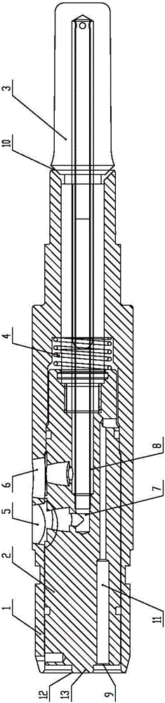
[0012] Such as figure 1 As shown, a mandrel in an injection blow molding machine includes a mandrel body 1, a mandrel body insert 2 movably arranged in the front half of the mandrel body 1 and a mandrel movably arranged at the end of the mandrel body 1 The head 3, the front end of the mandrel head 3 extends into the mandrel body 1, and the end extends into the mandrel body insert 2, the end is covered with a spring 4, and one end of the spring 4 is in conflict with the inner wall of the mandrel body 1, The other end is in conflict with the outer wall of the mandrel body insert 2, the mandrel body 1 is provided with a cooling liquid inlet 5 and a cooling liquid outlet 6, and a cooling water pipe is arranged in the mandrel body insert 2, and the cooling water pipe includes the inner layer of the water pipe 7 and the ou...


PUM


Abstract

The invention relates to a core rod in a hollow injection blow molding machine. The core rod comprises a core rod body, a core rod body insert movably arranged at the front half part in the core rod body, and a core rod head movably arranged at the tail end of the core rod body, wherein the front end of the core rod head extends in the core rod body insert, and is sleeved with a spring; the core rod body is provided with a cooling liquid inlet and a cooling liquid outlet; a cooling water pipe is arranged in the core rod body insert, and comprises a water pipe inner layer and a water pipe outer layer; the front half section of the cooling water pipe is arranged in the core rod body insert, and the back half section of the cooling water pipe is arranged in the core rod head; the water pipe inner layer and the water pipe outer layer are communicated at the end part of the back half section of the cooling water pipe; the core rod body is provided with an air inlet and an air outlet; the air outlet is formed in the position where the tail end of the core rod body is contacted with the core rod head; the air inlet is formed in the front end of the core rod body; an air pipe is arranged in the core rod body insert; the tail end of the air pipe is communicated with the internal of the core rod body, and the front end of the air pipe is communicated with the air inlet. The core rod provided by the invention solves the temperature control problem of the core rod head, and adopts a simple and practical structure and is lower in cost.

Description

technical field [0001] The invention relates to the technical field of injection blow molding machines, in particular to a mandrel in an injection blow molding machine. Background technique [0002] The basic working principle of the plastic molding machine is as follows: first form the parison, and then use compressed air (and stretch rod) to radially inflate (and axially stretch) the parison to make it close (stretch) and blow Plastic mold cavity, give the shape and size of the cavity to the product, and cool it. [0003] According to the method of parison molding, blow molding is divided into two categories: extrusion blow molding and injection blow molding; extrusion blow molding equipment (especially molds) has low cost and energy consumption, and can form large-volume containers and Products with complex shapes; injection blow-molded containers have high dimensional accuracy, do not form seams, and generally do not produce scraps. [0004] At present, the ordinary in...

Claims


Application Information

Patent Timeline
Patent Type & Authority Patents(China)
IPC IPC(8): B29C49/60B29C49/66
Inventor 陈春华张春宇刘刚
Owner JIANGSU VICTORY MACHINERY
Why Eureka
Try Eureka