Electric connector

An electrical connector and bonding technology, which is applied in the field of holding structures for fixing conductive terminals, can solve the problems of electrical connector safety hazards, plastics are easy to melt, and temperature rises, and achieve the effect of avoiding the risk of melting plastics and stabilizing the fixation

Active Publication Date: 2016-11-16
LINKCONN ELECTRONICS
View PDF7 Cites 12 Cited by
  • Summary
  • Abstract
  • Description
  • Claims
  • Application Information

AI Technical Summary

Problems solved by technology

The upper and lower insulating blocks carrying the holding terminals are made of plastic injection molded by plastic particles. In some application scenarios, USB Type-C electrical connectors need

Method used


Image

  • Electric connector
  • Electric connector
  • Electric connector

Examples


Embodiment Construction

[0024] The present invention will be further described below in conjunction with the accompanying drawings and embodiments.

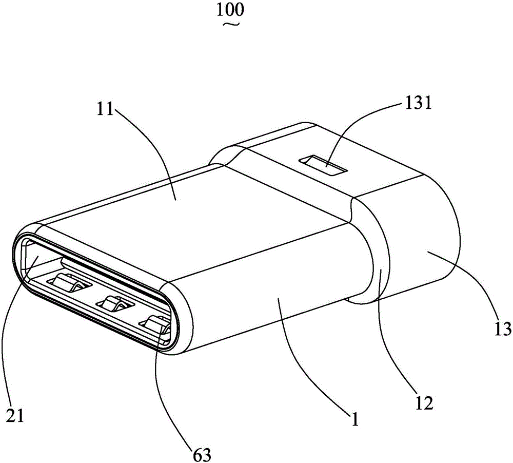
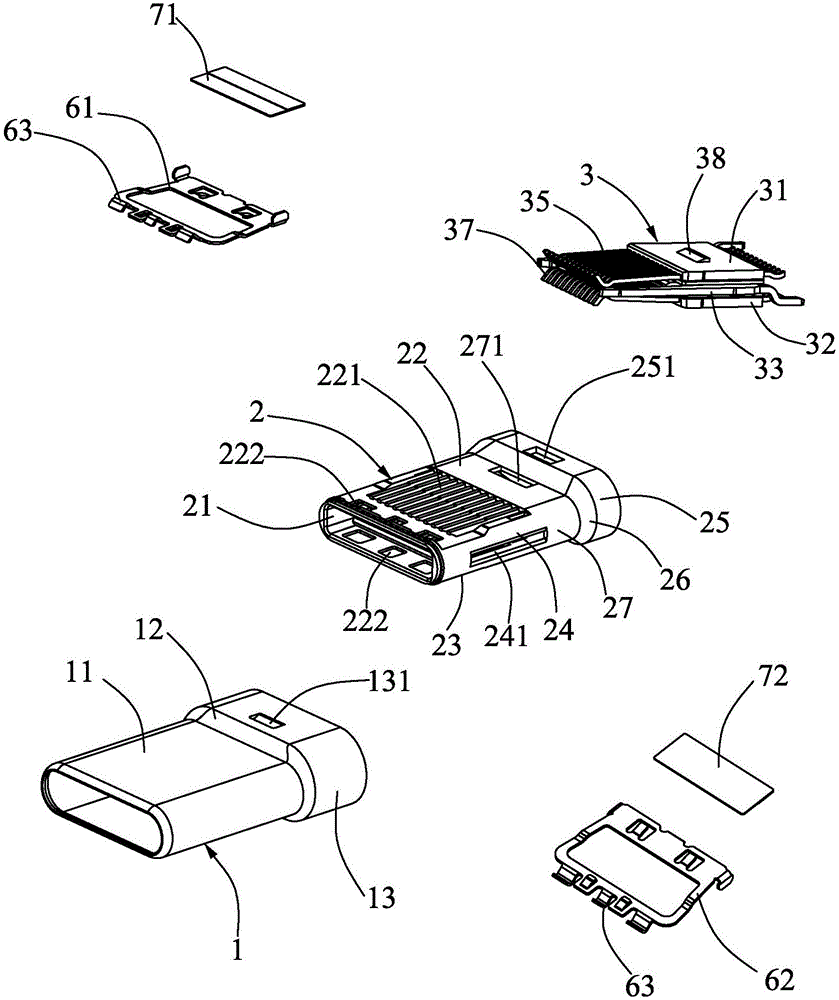
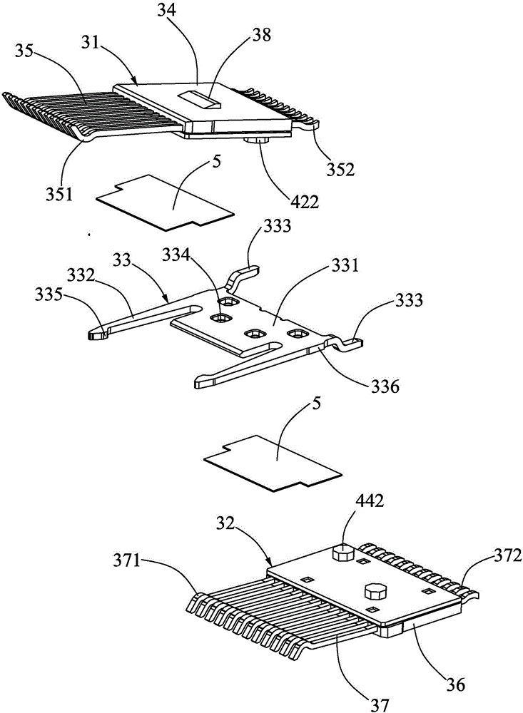
[0025] Such as Figure 1 to Figure 5 As shown, it is an electrical connector 100 according to the present invention, which includes: a metal shell 1 , an insulating body 2 fixedly installed in the metal shell 1 , and a terminal module 3 installed in the insulating body 2 .

[0026] The insulating body 2 includes a docking cavity 21 penetrating in front and rear directions, and the docking cavity 21 is configured to allow a docking tongue (not shown) to be inserted in two opposite directions. The insulating body 2 includes a top wall 22 , a bottom wall 23 , and two side walls 24 . The accommodating cavity 21 is surrounded by the top wall 22 , the bottom wall 23 , and the two side walls 24 . The top wall 22 and the bottom wall 23 are respectively provided with a row of terminal slots 221 and a plurality of through holes 222 located in front of the row of...


PUM


Abstract

The invention discloses an electric connector, which comprises an insulation body and a terminal module arranged in the insulation body. The insulation body comprises a butting cavity running through along the front and back direction. The butting cavity is configured to allow a butting tongue plate to be inserted in two opposite directions. The terminal module comprises an upper terminal module, a lower terminal module and a metal locking plate arranged between the upper terminal module and the lower terminal module. The upper terminal module comprises an upper ceramic plate and upper-line terminals fixedly arranged on the upper ceramic plate; the lower terminal module comprises a lower ceramic plate and lower-line terminals fixedly arranged on the lower ceramic plate; and the upper ceramic plate, the metal locking plate and the lower ceramic plate are bonded together through epoxy resin. Insulated plastic for bearing conductive terminals in the prior art are replaced by the ceramic, so that the risk that the plastic is melted by the conductive terminals due to high temperature can be prevented; and since the upper ceramic plate, the metal locking plate and the lower ceramic plate are bonded together through epoxy resin, the terminal module is fixed stably.

Description

technical field [0001] The invention relates to an electric connector, in particular to a holding structure for fixing a conductive terminal of the electric connector. Background technique [0002] The USB 3.0 promotion team (USB 3.0 Promoters) published the USB3.1 Specification on June 23, 2013, which defines the USB Type-C electrical connector. The highlight of the USB Type-C electrical connector is its slimmer design and support for double-sided insertion of the USB interface. [0003] For the prior art, please refer to the Chinese Utility Model Patent No. CN205178176U announced on November 18, 2015, which discloses a USB Type-C electrical connector, which includes an insulating body and a terminal module installed in the insulating body. The terminal module includes an upper terminal module, a lower terminal module and a metal locking plate sandwiched between the upper terminal module and the lower terminal module, wherein the upper terminal module includes an upper ins...

Claims


Application Information

Patent Timeline
IPC IPC(8): H01R13/46H01R13/40
CPCH01R13/40H01R13/46
Inventor 何龙彭勇锜
Owner LINKCONN ELECTRONICS
Why Eureka
Try Eureka