

Bottom box of switch or socket
A technology of bottom boxes and sockets, applied in the direction of electric switches, parts of connecting devices, electrical components, etc., can solve the problems of fire hazards, failure of extension parts, and affecting the appearance of decorative walls, etc., to achieve firm fixation and satisfy The requirements of fire codes and the effect of beautiful surface
- Summary
- Abstract
- Description
- Claims
- Application Information
AI Technical Summary
Problems solved by technology
Method used
Image

Examples
Embodiment 1
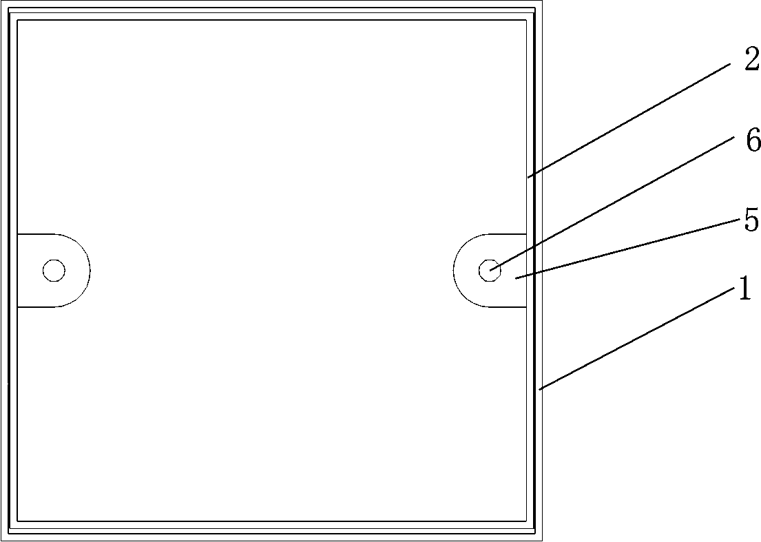
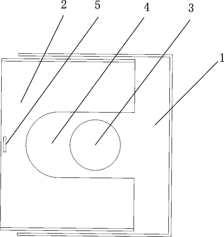
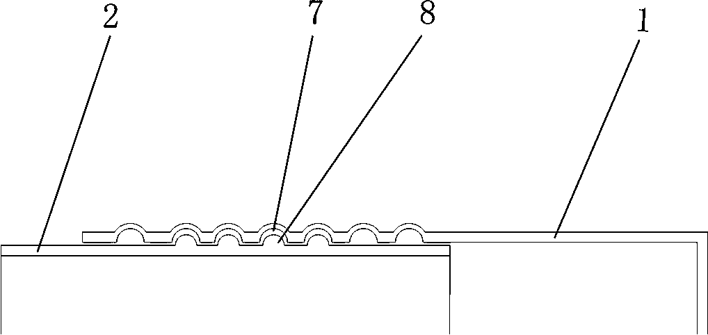
[0023] Embodiment one, see image 3 The telescopic fixing structure between the telescopic sleeve 2 and the box body 1 is as follows: the telescopic direction of the telescopic sleeve 2 is set as the axial direction of the bottom box, and the inner sides of the two opposite sides of the box body 1 are respectively provided with Several transverse grooves 7 perpendicular to the axial direction of the bottom box, and the outer sides of the opposite two sides of the telescopic sleeve 2 are respectively provided with several transverse convex strips 8 perpendicular to the axial direction of the bottom box. The shapes and sizes of the transverse grooves 7 match each other, and the number of the transverse protruding lines 8 is less than that of the transverse grooves 7 , and the transverse protruding lines 8 fall into the transverse grooves 7 . In this way, as long as the telescopic sleeve 2 is pushed toward the box body 1 with a certain amount of force, the transverse convex strip...
Embodiment 2
[0024] Embodiment two, see Figure 4 , the telescopic fixing structure between the telescopic sleeve 2 and the box body 1 is: it also includes positioning bolts 9, the inside of the side of the telescopic sleeve 2 is provided with a positioning block 10, and the inside of the side of the box body 1 1. There is a support block 11 near the bottom surface of the box body 1. Generally speaking, the telescopic sleeve 2 has a certain distance from the bottom surface of the box body 1, so it can be installed on the inner side of the side between the telescopic sleeve 2 and the bottom surface of the box body 1. Locate block 10. The positioning bolt 9 is rotatably fixed to one of the positioning block 10 or the support block 11 , and is screwed to the other of the positioning block 10 or the support block 11 . Like this, the distance between the positioning block 11 on the inner side of the telescopic sleeve 2 and the support block 12 on the inner side of the box body 1 can be adjuste...
PUM
 Abstract
Description
Claims
Application Information