
Motor support

A motor bracket and support frame technology, which is applied in the direction of the casing/cover/support, electrical components, electromechanical devices, etc., can solve the problems of affecting the use, single use of the motor, and large swing range of the motor, so as to achieve light connection and firm fixation , wide adaptability

Inactive Publication Date: 2015-01-21
THE 13TH CONSTR CO LTD OF CHINA NAT CHEM ENG
View PDF6 Cites 8 Cited by
  • Summary
  • Abstract
  • Description
  • Claims
  • Application Information

AI Technical Summary

Problems solved by technology

[0004] The function of the motor bracket is generally suitable for fixing the motor during the working process. Since the motor may be used in any position of the equipment, the motor bracket is required to fix the motor to be used at the designated position to facilitate the connection of subsequent equipment. The traditional motor The bracket is only matched with an ordinary connecting frame or a lead screw to directly raise the motor to the designated position and work. With the continuous development of the economy, all products are developing in a more precise direction. Therefore, the traditional motor bracket is due to the During the operation of the motor, the vibration generated by the whole bracket is relatively large, and the swing range of the motor is large, which affects the subsequent use. In addition, the motor bracket cannot change the height of the motor at any time, making the use of the motor more simple

Method used


Image

  • Motor support

Examples


Embodiment Construction

[0019] In order to describe the technical content, structural features, achieved goals and effects of the present invention in detail, the following will be described in detail in conjunction with the embodiments and accompanying drawings.

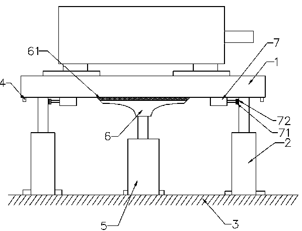
[0020] Please refer to the attached figure 1 , as shown in the accompanying drawings, the present invention provides a motor support, comprising a support platform 1, a longitudinal cylinder 2 and a support frame 3, the support platform 1 is provided with a bracket for fixing the motor, the support platform 1 is rectangular, and the longitudinal cylinder 2 Including a cylinder and a piston rod, the piston rod can slide in the cylinder, the longitudinal cylinder 2 is four, respectively arranged on the four corners of the rectangle, the longitudinal cylinder is fixed on the support frame 3, the piston rod The top of the top is fixed with the support platform 1;

[0021] The four corners of the support table 1 are provided with laser sen...


PUM


Abstract

A motor support comprises a supporting table, longitudinal air cylinders and a supporting rack. A support used for fixing a motor is arranged on the supporting table, and the supporting table is rectangular. Each longitudinal air cylinder comprises a cylinder body and a piston rod, wherein the piston rod can slide in the cylinder body. The air cylinders are fixed on the supporting rack, and the top ends of the piston rods are fixedly connected with the supporting table. Laser sensors are arranged at the four corners of the supporting table, a controller is arranged on the supporting rack, and the laser sensors are connected with the controller. A stabilizing air cylinder is further arranged on the supporting rack, and a stabilizing rack is arranged on the top of a piston rod of the stabilizing air cylinder. According to the motor support, the supporting table can be precisely and quickly moved to a specified position, precise fine adjustment can be conducted according to specific work needs, so that connection of the motor is more convenient, in the moving process of the motor, the entire supporting table is fixed very firmly, and the fact that connection is affected by shaking can not happen.

Description

[0001] technical field [0002] The invention mainly relates to an adjusting mechanism for fixing a motor, in particular to a motor bracket used in engineering. [0003] Background technique [0004] The function of the motor bracket is generally suitable for fixing the motor during the working process. Since the motor may be used in any position of the equipment, the motor bracket is required to fix the motor to be used at the designated position to facilitate the connection of subsequent equipment. The traditional motor The bracket is only matched with an ordinary connecting frame or a lead screw to directly raise the motor to the designated position and work. With the continuous development of the economy, all products are developing in a more precise direction. Therefore, the traditional motor bracket is due to the During the operation of the motor, the entire support generates large vibrations, and the motor swings greatly, which affects subsequent use. In addition, th...

Claims


Application Information

Patent Timeline
IPC IPC(8): H02K5/00H02K5/24H02K5/26
CPCH02K5/24H02K5/26
Inventor 曾楠王群伟宋楠
Owner THE 13TH CONSTR CO LTD OF CHINA NAT CHEM ENG
Learn More