Electric component locking and installation device
A technology for installing equipment and components, applied in the field of locking and installing equipment for power components, can solve the problems of inconvenient disassembly, aging bolt structure, small space inside the instrument box, etc., and achieve the effect of convenient laying, convenient installation and locking
- Summary
- Abstract
- Description
- Claims
- Application Information
AI Technical Summary
Problems solved by technology
Method used
Image
Examples
Embodiment 1
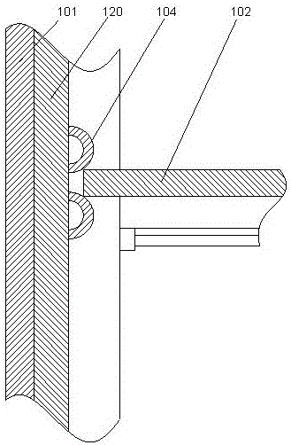
[0019] Such as figure 1 As shown in / 2, a power element locking and installation device includes a mounting plate 101 and a support plate 102 arranged on the mounting plate 101. The two mounting plates 101 are oppositely arranged, and the two mounting plates 101 Mounting strips 103 are respectively provided on the opposite end faces, and the mounting strips 103 are perpendicular to the plane where the mounting plate 101 is located, and spaced positioning pieces 104 are arranged inside the mounting strips 103. The positioning piece 104 is made of two elastic metal sheets arranged up and down. The elastic metal sheet is in an arc-shaped structure arched toward the inside of the mounting plate 101, and the two ends of the elastic metal sheet located at the lower part are fixedly connected. On the described installation strip 103, the lower end of the elastic metal sheet positioned at the upper part is fixedly connected to the described installation strip 103, and its upper end is...
Embodiment 2
[0024] In this embodiment, for the convenience of installation, preferably, a stud 111 is provided on the upper end surface of the column 106, and an end cap 112 is arranged above the stud 111, and the end cap 112 is hollow and annular Structure, the four corners of the end cover 112 are respectively provided with through holes, and the upper ends of the studs 111 respectively pass through the corresponding through holes and are connected with the end cover 112 through nuts. By adopting the end cover structure, the upper end surface of the power meter can be protected. Due to the hollow ring structure, the display part or switch part of the electric meter can be relatively suspended inside the hollow structure of the end cover, which is convenient for operation and observation.
[0025] In this embodiment, in order to prevent the upper end of the instrument from colliding with the end cover when vibration occurs, preferably, an annular buffer pad 113 is provided on the lower e...
Embodiment 3
[0028] In this embodiment, in order to facilitate the laying of lines, preferably, a wiring groove 116 is provided on the lower end surface of the support plate 102, and a wiring hole communicating with the wiring groove 116 is provided on the support plate 102 117.
[0029] The lines connected to the instruments can be laid through the wiring troughs, so that the lines can be connected to the line adapter board through the wiring troughs and wiring holes, which facilitates the classified connection of the lines, thus facilitating the maintenance and management of different instruments in the overall structure.
PUM
 Abstract
Description
Claims
Application Information
 - R&D
- Intellectual Property
- Life Sciences
- Materials
- Tech Scout
- Unparalleled Data Quality
- Higher Quality Content
- 60% Fewer Hallucinations
Browse by: Latest US Patents, China's latest patents, Technical Efficacy Thesaurus, Application Domain, Technology Topic, Popular Technical Reports.
© 2025 PatSnap. All rights reserved.Legal|Privacy policy|Modern Slavery Act Transparency Statement|Sitemap|About US| Contact US: help@patsnap.com


