
Liquid ejection head, channel member thereof, manufacturing method, and liquid ejection device

A technology of liquid jet head and flow channel components, which is applied in the field of inkjet recording devices and liquid jet devices, and can solve the problems of flow channel position deviation, ink leakage, position deviation, etc.

Active Publication Date: 2019-06-25
SEIKO EPSON CORP
View PDF14 Cites 0 Cited by
  • Summary
  • Abstract
  • Description
  • Claims
  • Application Information

AI Technical Summary

Problems solved by technology

[0005] However, the first sealing member is pressed in the lamination direction to connect the third channel member to the second channel member, and the second sealing member is pressed in the first direction and the second direction to store the liquid. When the first flow path member such as a unit is connected to the second flow path member, if the dimensions of the components constituting the flow path member deviate, positional deviation occurs at the connection portion of the flow path and ink leakage occurs. The problem
[0006] In addition, in order to form a complicated flow channel in the second flow channel member, when the second flow channel member is formed by laminating a plurality of members, there may be dimensional deviation or Possibility of positional deviation at the connection part of the runner due to errors such as positional deviation during lamination

Method used


Image

  • Liquid ejection head, channel member thereof, manufacturing method, and liquid ejection device
  • Liquid ejection head, channel member thereof, manufacturing method, and liquid ejection device
  • Liquid ejection head, channel member thereof, manufacturing method, and liquid ejection device

Examples


Embodiment approach 1

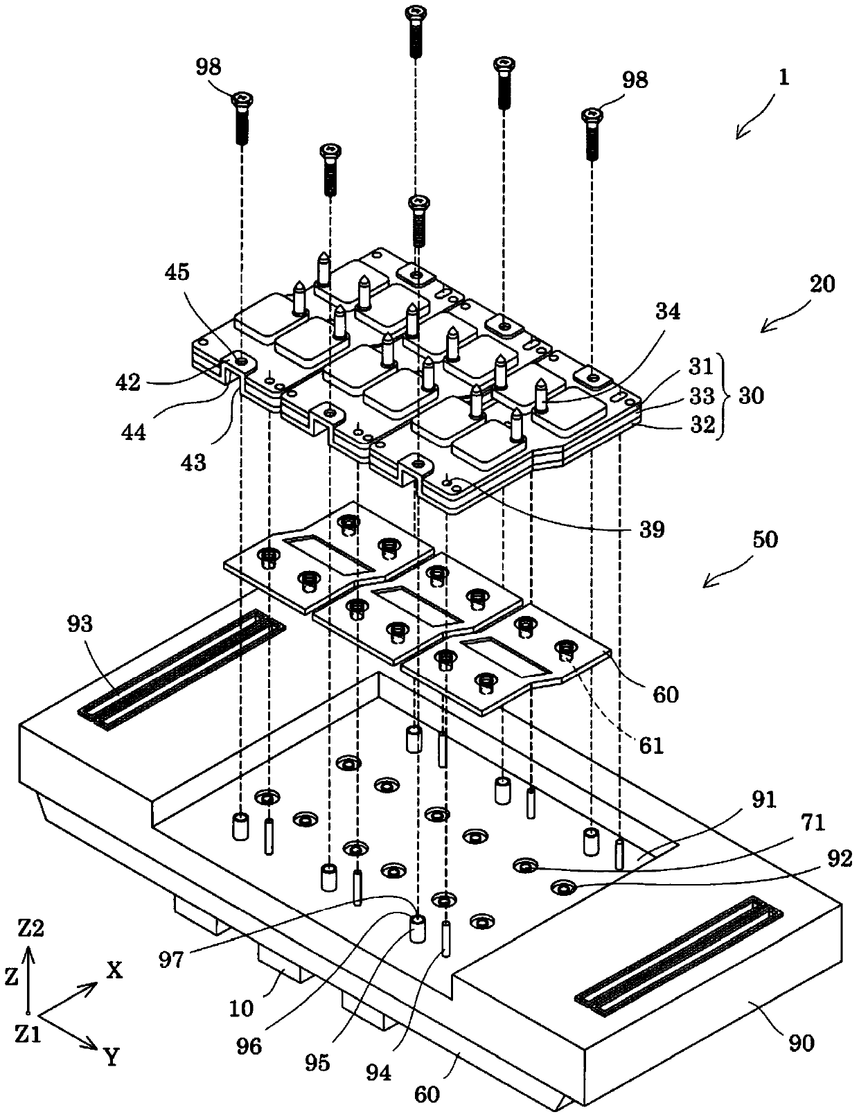
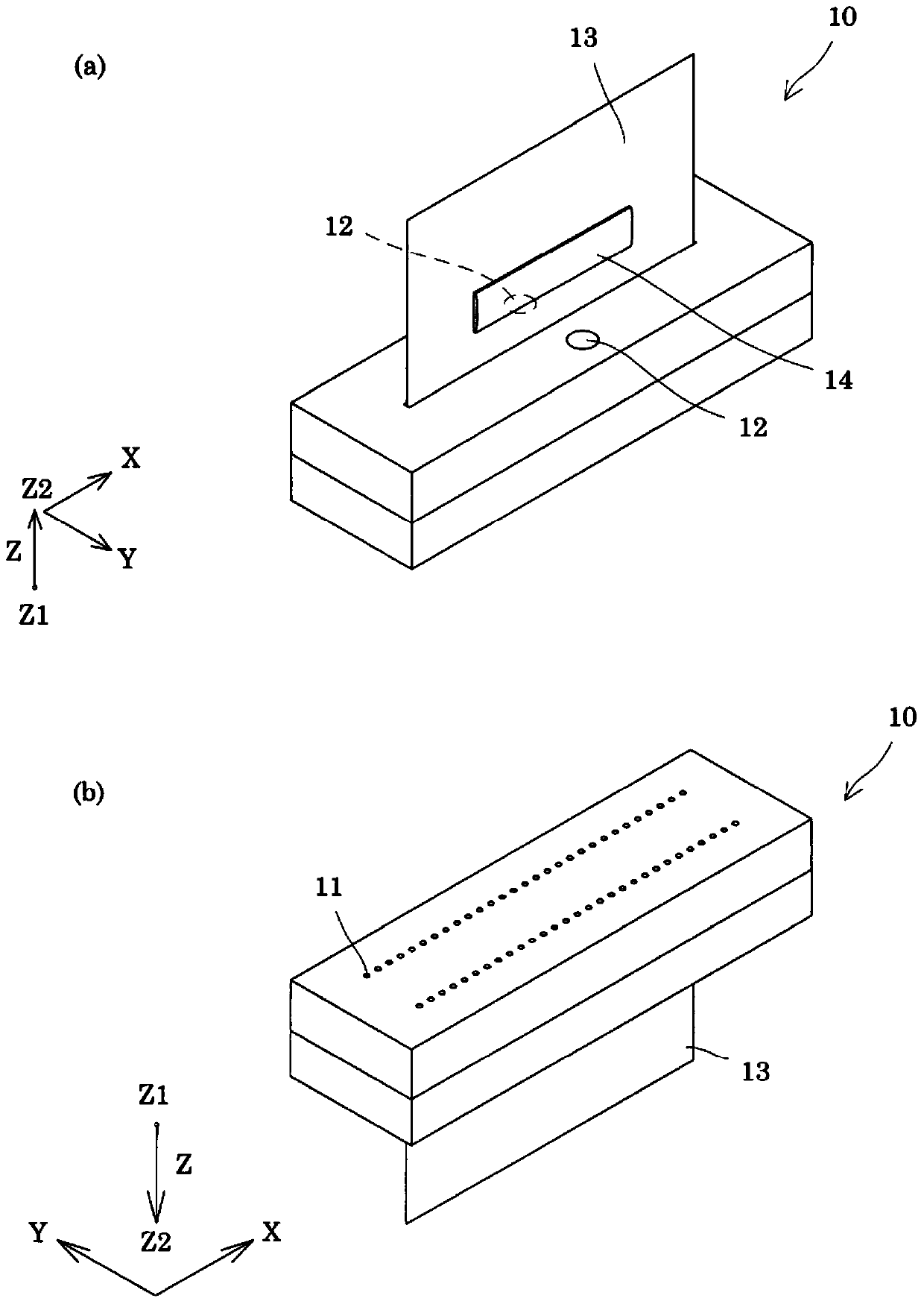
[0062] figure 1 Is an exploded perspective view of an inkjet recording head as an example of the liquid ejection head according to Embodiment 1 of the present invention, figure 2 It is a perspective view of the head body.

[0063] Such as figure 1 As shown, an inkjet recording head 1 (hereinafter also simply referred to as a recording head 1) as an example of the liquid ejection head of the present embodiment includes: a plurality of head bodies 10 that eject ink droplets from nozzles; a flow path member 20, It holds a plurality of head main bodies 10 and is provided with a liquid flow path for supplying liquid to the head main body 10.

[0064] Such as figure 2 As shown, in the head main body 10, nozzle rows formed by nozzles 11 that eject ink droplets as liquid are arranged side by side on one surface, and two rows are arranged side by side in a direction intersecting the direction in which the nozzles 11 are arranged side by side. Here, in one nozzle row, the direction in whic...


PUM


Abstract

A liquid ejecting head includes a second flow-path-member comprising a second flow-path in communication with first and third flow-paths provided in first and second flow-path-members, the second flow-path-member stacked with the third flow-path-members in a stacking direction. A boundary between the first and second flow-path is tightly sealed by a first sealing-member. A boundary between the second and third flow-path is tightly sealed by a second sealing-member. The second flow-path-member includes a first substrate for positioning itself to the third flow-path-member in first and second directions intersecting with the stacking direction, and a second substrate for positioning itself to the third flow-path-member in the stacking direction. The first substrate is pressed against in the first and second directions by one of the first and second sealing-member. The second substrate is pressed against in the stacking direction by another one of the first and second sealing-member.

Description

[0001] This application claims the priority of Japanese Patent Application No. 2015-100440 filed on May 15, 2015. The entire disclosure of Japanese Patent Application No. 2015-100440 is incorporated herein by reference. Technical field [0002] The present invention relates to a liquid ejecting head that ejects liquid from a nozzle, a flow path member, a manufacturing method, and a liquid ejecting device, and more particularly to an inkjet recording head that ejects ink as a liquid, and a flow path member, a manufacturing method thereof, and Inkjet recording device. Background technique [0003] As a representative example of a liquid ejecting head that ejects liquid, there is an inkjet recording head that ejects ink. An inkjet recording head is proposed, which includes: a head body that ejects ink droplets from nozzles; and a flow path member that is fixed to the head body and supplies the head body from a liquid storage unit such as an ink cartridge that stores ink. Ink (for e...

Claims


Application Information

Patent Timeline
Patent Type & Authority Patents(China)
IPC IPC(8): B41J2/14B41J2/16B41J2/01
CPCB41J2/175B41J2202/19
Inventor 钟江贵公
Owner SEIKO EPSON CORP
Learn More