Oil heated ironing roller

A technology of ironing rollers and oil heating, which is applied in textiles, papermaking, and fabric surface trimming, etc. It can solve the problems of affecting product quality, large temperature difference between the two ends of the ironing roller, and high energy consumption, so as to save high power consumption and temperature conduction The effect of balanced and reasonable conduction structure

Active Publication Date: 2018-12-14
LIANYUNGANG CITY RUNIAN MACHINE
View PDF6 Cites 0 Cited by
  • Summary
  • Abstract
  • Description
  • Claims
  • Application Information

AI Technical Summary

Problems solved by technology

At present, the electric heating roller uses 24 electric heating tubes, and the power consumption is about 60KW. The energy consumption is high and the production cost is high, which directly affects the economic benefits of the production enterprise.
Aiming at the problem of high energy consumption of electrically heated ironing rollers, an oil ironing roller has been developed, which effectively reduces energy consumption
However, the currently used oil ironing roller has a large temperature difference between the two ends of the ironing roller, the control effect is not ideal, and the product quality is affected, and the technology needs to be further improved.
[0003] For example, a kind of ironing roller in patent number 201420014264.8 realizes the ironing of fabrics and saves high-power consumption. However, the oil ironing roller used has a large temperature difference between the two ends of the ironing roller, and the control effect is not ideal, which affects the product quality.

Method used


Image

  • Oil heated ironing roller
  • Oil heated ironing roller
  • Oil heated ironing roller

Examples


Embodiment 1

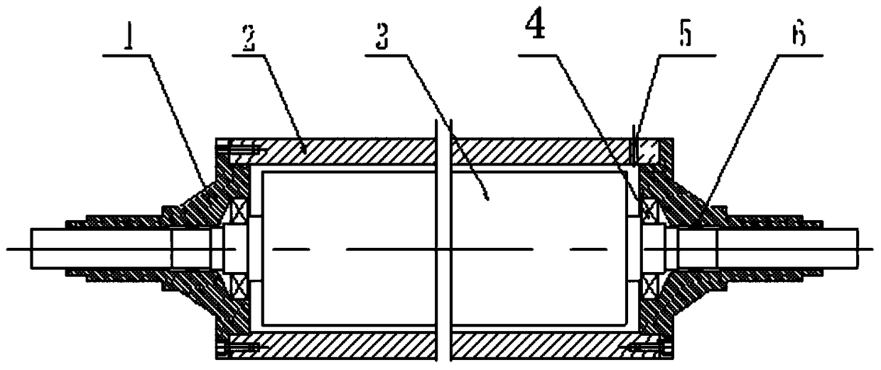
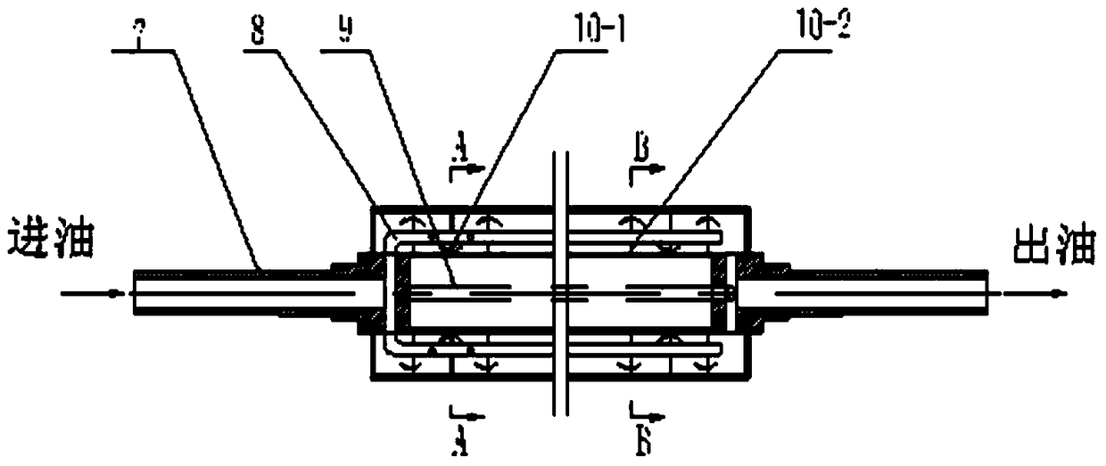
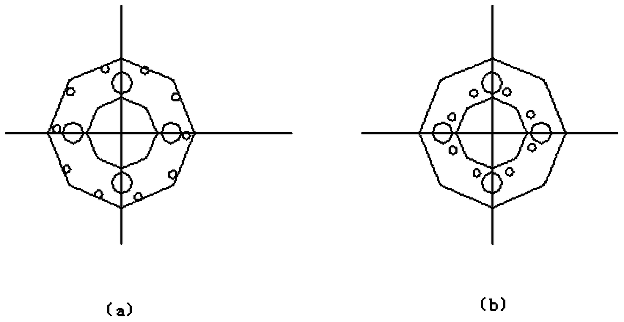
[0018] An oil-heated ironing roller, including a shaft head 1, a ironing roller shell 2, a heat transfer oil liner 3, a bearing 4, and a skeleton oil seal 6; The oil liner 3 passes through the ironing roller shell 2 and the shaft head 1 at both ends and rotates with the ironing roller shell 2 and the shaft head 1. The shaft end on the two ends of the heat transfer oil liner 3 and the shaft head 1 hole Bearings 4 and skeleton oil seals 6 are arranged in sequence between them; on the side wall of the ironing roller shell 2, there is an oil filling hole 5 communicating with the gap between the ironing roller shell 2 and the heat transfer oil liner 3, and the heat transfer oil liner 3 Between the two inner shaft ends is the main shaft 7, the main shaft 7 is covered with a splitter plate perpendicular to the main shaft, and the splitter holes on the adjacent splitter plates are sequentially distributed on the inner or outer ring edges of the splitter plate, characterized in that: T...

Embodiment 2

[0022] An oil-heated ironing roller, including a shaft head 1, a ironing roller shell 2, a heat transfer oil liner 3, a bearing 4, and a skeleton oil seal 6; The oil liner 3 passes through the ironing roller shell 2 and the shaft head 1 at both ends and rotates with the ironing roller shell 2 and the shaft head 1. The shaft end on the two ends of the heat transfer oil liner 3 and the shaft head 1 hole Bearings 4 and skeleton oil seals 6 are arranged in sequence between them; on the side wall of the ironing roller shell 2, there is an oil filling hole 5 communicating with the gap between the ironing roller shell 2 and the heat transfer oil liner 3, and the heat transfer oil liner 3 Between the two inner shaft ends is the main shaft 7, the main shaft 7 is covered with a splitter plate perpendicular to the main shaft, and the splitter holes on the adjacent splitter plates are sequentially distributed on the inner or outer ring edges of the splitter plate, characterized in that: T...


PUM


Abstract

The invention discloses an oil heating lustring roller which comprises a spindle nose, a lustring roller shell, a heat conductive oil inner container, a bearing and a framework oil seal. A main shaft is arranged between the two shaft ends in the heat conductive oil inner container and sleeved with flow dividing plates perpendicular to the main shaft. Flow dividing holes in every two adjacent flow dividing plates are sequentially distributed in the inner ring edges or the outer ring edges of the flow dividing plates. Oil guide pipes are symmetrically arranged outside the main shaft and penetrate through the flow dividing plates. One end of each oil guide pipe is connected with the oil inlet of the main shaft, and the other end of each oil guide pipe is close to the oil outlet end of the main shaft. An oil return pipe is arranged outside the main shaft and penetrates through the flow dividing plates. One end of the oil return pipe is connected with the oil outlet of the main shaft, and the other end of the oil return pipe is close to the oil inlet end of the main shaft. The oil heating lustring roller is more reasonable in heat conductive oil conduction structure and more uniform in temperature conduction; due to the oil outlet in the inlet end of the oil guide pipe, the temperature difference of the two ends of the lustring roller is compensated for, the surface temperature of the lustring roller is more uniform, and the lustring quality of a fabric can be effectively improved.

Description

technical field [0001] The invention belongs to the field of textile post-finishing mechanical ironing machines, in particular to an oil heating ironing roller. Background technique [0002] The ironing roller is a core part of the plush fabric ironing machine, and its function is to straighten the wool surface fibers of the plush fabric and make it elastic and glossy. The heating method of the traditional ironing roller is electric heating, and the roller body reaches the working temperature through heating by the electric heating tube inside the roller body. At present, the electric heating roller uses 24 electric heating tubes, and the power consumption is about 60KW. The energy consumption is high and the production cost is high, which directly affects the economic benefits of the production enterprise. To solve the problem of high energy consumption of electrically heated ironing rollers, an oil ironing roller has been developed, which effectively reduces energy consum...

Claims


Application Information

Patent Timeline
Patent Type & Authority Patents(China)
IPC IPC(8): D06C15/08
Inventor 张昊张波席春玲
Owner LIANYUNGANG CITY RUNIAN MACHINE
Why Eureka
Try Eureka