Electromagnetic induction ironing roller

An electromagnetic induction and ironing roller technology, which is applied in the direction of textiles, papermaking, and fabric surface trimming, can solve the problems of oil heating ironing roller development constraints, high energy consumption, and high production costs, so as to save high-power electricity, rollers, etc. The surface temperature is constant and the effect of improving the quality of scalding

Active Publication Date: 2015-11-18
LIANYUNGANG CITY RUNIAN MACHINE
View PDF7 Cites 0 Cited by
  • Summary
  • Abstract
  • Description
  • Claims
  • Application Information

AI Technical Summary

Problems solved by technology

At present, electric heating rollers are used. Since the electric heating power of a roller body is about 60KW, the energy consumption is high and the production cost is high. In addition, due to the shortage of electricity and the difficulty in approval and investment of electric capacity expansion, users increase production capacity and technology. The transformation encountered great restrictions; secondly, the surface temperature of the electric heating roller was uneven due to the unbalanced heating of the resistance wire in the roller body, and even the temperature differed greatly.
Oil-heated ironing rollers need kerosene-fired boilers to provide heat. Using oil-heated ironing rollers, such as new projects, requires a large investment, and secondly, coal burning has an impact on the atmospheric environment. Therefore, the development of oil-heated ironing rollers is restricted.

Method used


Image

  • Electromagnetic induction ironing roller
  • Electromagnetic induction ironing roller

Examples


Embodiment Construction

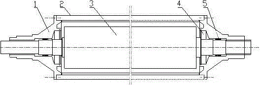
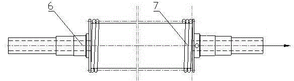
[0010] Such as figure 1 with figure 2 As shown, the electromagnetic induction scalping roller designed in the present invention includes a scalping roller shell 2, two skeleton oil seals 5, two shaft heads 1, two bearings 4, two flanges, a high temperature coil 7, and a coil core 3. And the rotating core shaft 6 passing through the coil rotating core 3; wherein the length of the rotating core core shaft 6 is greater than the length of the coil rotating core 3, and the coil rotating core 3 is located at the center of the rotating core core shaft 6; The length of the roller shell 2 is adapted to the length of the coil rotor core 3. The scalping roller shell 2 is sleeved outside the coil rotor core 3; one end of each shaft head 1 is in the shape of a boss. The two ends are respectively connected with the boss portion of each shaft head 1, and the two ends of the rotating core mandrel 6 respectively pass through the shaft head 1 located at the two ends of the scalping roller shell...


PUM


Abstract

The invention relates to an electromagnetic induction iron finishing roller which comprises an iron finishing roller shell (2), two framework oil seals (5), two spindle heads (1), two bearings (4), two flanges, a high-temperature coil (7), a coil rotary core (3) and a rotary core mandrel (6) penetrating through the coil rotary core (3). The bearings (4) and the framework oil seals (5) are arranged in the two spindle heads (1) respectively, and the center line of each spindle head (1), the center line of each framework oil seal (5), each bearing (4), the center line of the iron finishing roller shell (2) and the center line of the coil rotary core (3) are in the same straight line; the two ends of an interlayer inner container of the iron finishing roller shell (2) are provided with an oil filling hole and an oil overflow hole respectively, and the high-temperature coil (7) is wound on the coil rotary core (3). The designed electromagnetic induction iron finishing roller is little in consumption power and remarkable in power conservation effect.

Description

Technical field [0001] The invention belongs to the field of textile machinery ironing machines, especially electromagnetic induction ironing rollers. Background technique [0002] The ironing roller is a core component of the plush fabric ironing machine. Its function is to straighten the wool surface fibers of the plush fabric and make it smooth and full of elasticity and luster. At present, the heating method of the scalding roller of the scalding machine at home and abroad is electric heating and oil heating, that is, the roller body is heated to the working temperature through the electric heating tube inside the roller body and the heat conduction oil heating. At present, electric heating scalding rollers are used. Because the electric heating power of a roller body is about 60KW, the energy consumption is high, the production cost is high, and due to the shortage of electricity and the difficulty of approval and investment for power expansion, users increase production cap...

Claims


Application Information

Patent Timeline
Patent Type & Authority Patents(China)
IPC IPC(8): D06C15/08
Inventor 张昊张波唐考成席春玲
Owner LIANYUNGANG CITY RUNIAN MACHINE
Why Eureka
Try Eureka