Thermal propagation mitigation for HV battery modules

A high-voltage battery and battery unit technology, applied in the direction of secondary batteries, battery pack components, battery boxes/coats, etc., can solve problems such as not providing multi-dimensional solutions

Active Publication Date: 2016-11-23
GM GLOBAL TECH OPERATIONS LLC
View PDF3 Cites 0 Cited by
  • Summary
  • Abstract
  • Description
  • Claims
  • Application Information

AI Technical Summary

Problems solved by technology

While this approach works reasonably well, prior art approaches to addressing fire protection offer few multidimensional solutions to the problem

Method used


Image

  • Thermal propagation mitigation for HV battery modules
  • Thermal propagation mitigation for HV battery modules
  • Thermal propagation mitigation for HV battery modules

Examples


Embodiment Construction

[0014] Reference will now be made in detail to presently preferred combinations, embodiments and methods of the invention, which constitute the best modes currently known to the inventors for carrying out the invention. The figures are not necessarily drawn to scale. It is to be understood, however, that the disclosed embodiments are merely exemplary aspects of the invention, which may be embodied in various and alternative forms. Therefore, specific details disclosed herein are not to be interpreted as limiting, but merely as a representative basis for any aspect of the invention and / or as a representative basis for teaching one skilled in the art to variously employ the invention.

[0015] Except in the examples, or where otherwise expressly indicated, all quantities in this specification indicating amounts of material or conditions of reaction and / or use are to be understood as modified by the word "about" describing the broadest scope of the invention. Practice within the...


PUM


Abstract

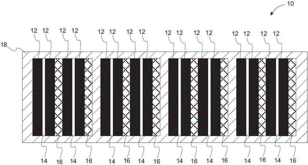
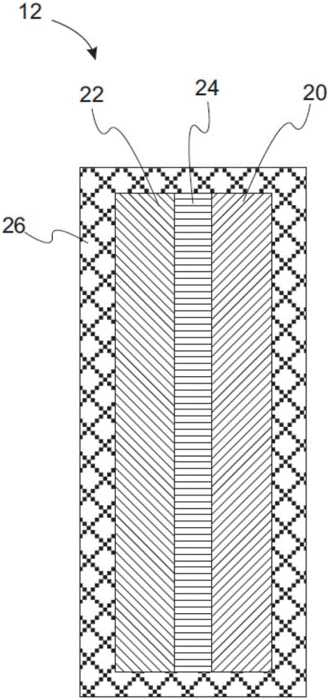
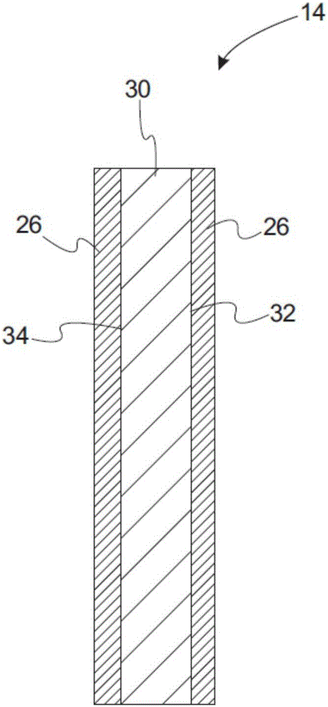
A high voltage battery module includes a plurality of battery cells, a plurality of cooling fins dispersed between the battery cells, and a frame for holding the plurality of battery cells and the plurality of fins. An intumescent layer is proximate to at least one battery module component selected from the battery cells, the plurality of cooling fins, and the frame. The intumescent layer includes sodium silicate having formula Na2SiO3, pentaerythitol, a resin that is cross-linked by melamine, boron nitride particles, and triammonium phosphate.

Description

technical field [0001] In at least one aspect, the present invention relates to intumescent coatings for electronic components, and in particular to intumescent coatings for circuit boards and fuses that are subject to overheating and fire hazards. Background technique [0002] Many electronic devices are subject to overheating providing some fire hazard. For example, a large amount of heat can be generated by a short circuit in the device. Such short circuits can occur through inadvertent contact of electronic components with water from coolant leaks or moisture buildup. In addition, failed components may cause high electrical potentials, which may also create a fire hazard or thermal runaway. [0003] Prior art approaches attempt to address fire hazards in electronic devices in a number of ways. For example, an electronic device may be enclosed in a flameproof enclosure. While this approach works reasonably well, the prior art approaches to fire protection offer few mu...

Claims


Application Information

Patent Timeline
Patent Type & Authority Applications(China)
IPC IPC(8): H01M2/10H01M50/117H01M50/121H01M50/122H01M50/131H01M50/204H01M50/222H01M50/227H01M50/229H01M50/293
CPCH01M10/6555H01M50/227H01M50/117H01M50/131H01M50/122H01M50/229H01M50/293H01M50/121H01M50/222H01M50/204H01M10/6551H01M10/613H01M10/653Y02E60/10C09D5/185
Inventor S·A·赛义德H·K·菲勤吉姆M·H·阿卜杜勒-哈米德E·P·卡尔德隆
Owner GM GLOBAL TECH OPERATIONS LLC
Why Eureka
Try Eureka