Installation method and installation structure of large span space rebate continuous steel truss

An installation method and installation structure technology, which are applied to truss-type structures, girders, trusses, etc., can solve the problems of cumulative installation errors, increase the uncertainty of subsequent segment cantilever benchmarks, and affect the control of engineering implementation. Installation control, increased flexibility, reduced installation deviation effect

Active Publication Date: 2016-12-07
CHINA CONSTR EIGHT ENG DIV CORP LTD
View PDF4 Cites 5 Cited by
  • Summary
  • Abstract
  • Description
  • Claims
  • Application Information

AI Technical Summary

Problems solved by technology

[0004] The purpose of the present invention is to overcome the defects of the prior art, to provide an installation method and installation structure of a large-span space drop-down continuous steel truss, to solve the problem of easy installation accumulation errors in the segmented cantilever installation method in the prior art, and to increase the The uncertainty of the follow-up segmental cantilever benchmark seriously affects the control of project implementation

Method used


Image

  • Installation method and installation structure of large span space rebate continuous steel truss
  • Installation method and installation structure of large span space rebate continuous steel truss
  • Installation method and installation structure of large span space rebate continuous steel truss

Examples


Embodiment Construction

[0042] The present invention will be further described below in conjunction with the accompanying drawings and specific embodiments.

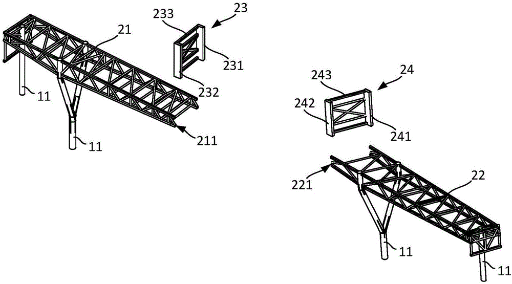
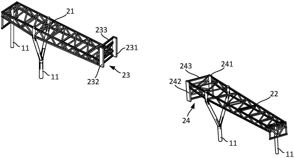
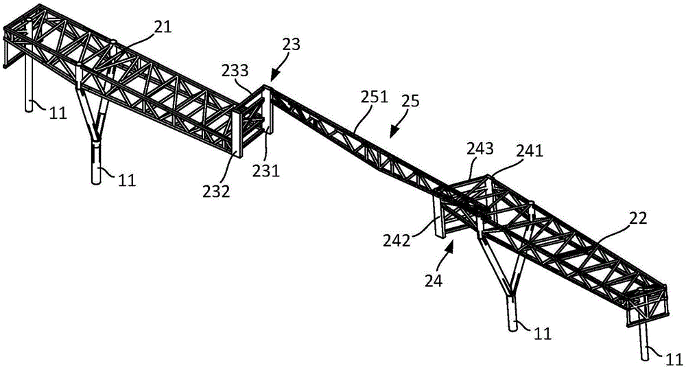
[0043] The invention provides an installation method and installation structure of a large-span continuous steel truss truss, which overcomes the shortcomings of the current large-span continuous steel truss cantilever installation technology, simplifies the installation process, and aims at high headroom and large-span spaces. According to the characteristics of continuous roof steel trusses, the method of conventional axial segmental cantilever installation is improved, and an outrigger cantilever installation technology suitable for large-span space drop-down continuous steel truss high-altitude rapid closing is formed. The present invention reuses the vertical bearing capacity of the roof column in the structural main body at both ends of the steel truss, adopts the cantilever installation of the apex span truss, and then installs the drop-d...


PUM


Abstract

The invention relates to an installation method of a large span space rebate continuous steel truss. The installation method comprises the following steps: lifting a low-end span truss cantilever and a high-end span truss cantilever on main structural bodies at the two ends of the steel truss, and the low-end span truss cantilever and the high-end span truss cantilever extending out of the corresponding main structural bodies to form a low-end cantilever end and a high-end cantilevering end; lifting a first rebate davit at the low-end cantilevering end; lifting a second rebate davit at the high-end cantilevering end, and lifting a midspan truss beam between the first rebate davit and the second rebate davit. The truss cantilevers are firstly installed on the main structural bodies at the low end and the high end to form the cantilevering ends, and the installation method that the midspan truss beam is not supported and closed by utilizing the rebate davits is realized, so that the problem that the installation accumulation error is easily generated by the cantilevering end deflection accumulation in the existing method is solved, and the cantilevering and closing of the large span space truss body are formed once, and thus the installation and control are easy.

Description

technical field [0001] The invention relates to the field of building construction, in particular to an installation method and installation structure of a large-span space step-down continuous steel truss. Background technique [0002] With the rapid development of the current building steel structure, the large-scale space steel truss roof system is widely used in various shopping plazas, conference centers and stadium projects due to its strong spanning ability, small space volume, high degree of industrialization, and superior load performance. and so on have been widely used in design. In order to reduce the occupancy of the lower space during the operation process and facilitate the cross-development of the production process, the installation and construction of the project often adopts the method of high-altitude cantilever installation. [0003] The current cantilever installation method is to process the axial units of the continuous truss into sections, and then ...

Claims


Application Information

Patent Timeline
Patent Type & Authority Applications(China)
IPC IPC(8): E04B1/19E04B1/342E04C3/11
CPCE04B1/19E04B1/342E04C3/11
Inventor 周光毅李洪杰张强刘旭赵传莹
Owner CHINA CONSTR EIGHT ENG DIV CORP LTD
Why Eureka
Try Eureka