
Electric gate valve

A technology of electric gate and valve body, applied in the direction of sliding valves, valve details, valve devices, etc., can solve the problems that affect the stability of production line conditions and product quality, poor sealing effect, and tight sealing, etc., to achieve uniform force , Good sealing effect, avoiding the effect of valve stuck

Active Publication Date: 2018-10-02
CBMI CONSTR
View PDF6 Cites 0 Cited by
  • Summary
  • Abstract
  • Description
  • Claims
  • Application Information

AI Technical Summary

Problems solved by technology

[0002] Common sealing devices for electric gate valves that can be used for high temperature are generally installed on the upper part of the lower valve body. When wear or volume changes occur, it is easy to cause problems such as poor sealing and poor sealing effect, thus affecting the stability of the entire production line. and product quality

Method used


Image

  • Electric gate valve
  • Electric gate valve
  • Electric gate valve

Examples


Embodiment Construction

[0016] The present invention will be further described below in conjunction with embodiments, and the purpose is only to better understand the content of the present invention. Therefore, the examples cited do not limit the protection scope of the present invention.

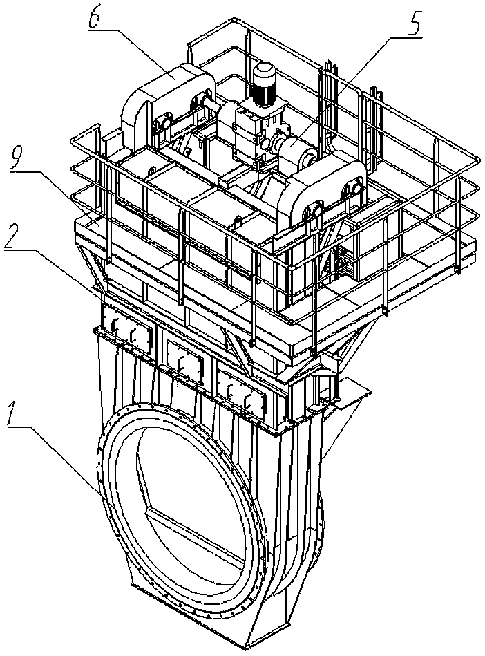
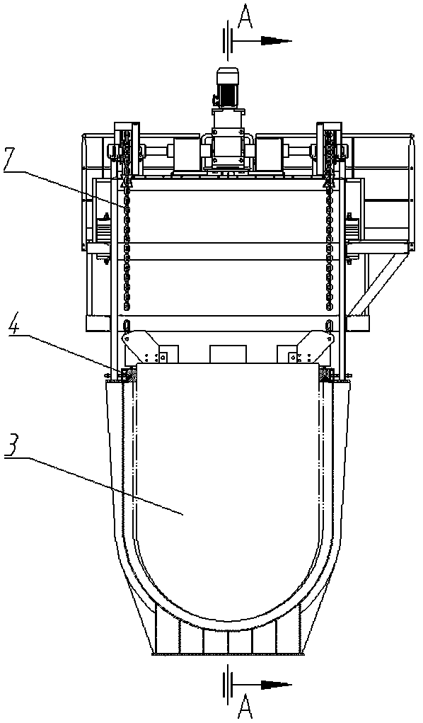
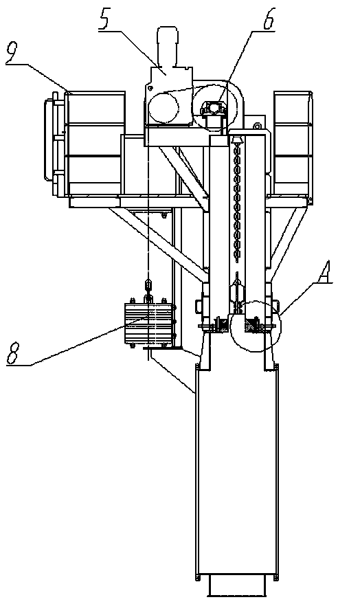
[0017] See figure 1 , figure 2 , image 3 , Figure 4 , The valve plate 3 is installed in the lower valve body 1, and the opening and closing of the valve is controlled by the up and down movement in the lower valve body 1. The lower valve body 1 and the upper valve body 2 are connected by bolts to form a valve body, and the upper valve body 2 is installed with The platform 9, the driving device 5 and the driven wheel device 6 are installed on the platform 9. The driving device 5 is composed of double motors. Two sets of the driven wheel device 6 are arranged symmetrically on both sides of the driving device 5. The valve plate 3 is respectively connected by a chain 7 It is connected to the two sets of driven wheel ...


PUM


Abstract

The invention relates to a pipe gate valve, in particular to an electric gate valve used in a high-temperature environment. The electric gate valve comprises a valve plate, a lower valve body, an upper valve body, a platform, a driving device, driven wheel devices, counterweight devices and a sealing device, wherein the sealing device is mounted on the upper part of the lower valve body and comprises ceramic fibers, a pressing plate, a pressing rod, a push plate, a push rod and locking nuts; the ceramic fibers are mounted on the upper part of the lower valve body; the pressing plate is mounted on the upper parts of the ceramic fibers through the pressing rod and the locking nuts and is used for adjusting the sealing effect of the ceramic fibers in the radial direction; and the push plate is mounted on the other sides of the ceramic fibers relative to the lower valve body through the push rod and the locking nuts, and is used for adjusting the sealing effect of the ceramic fibers in the axial direction. The sealing effect of the ceramic fibers can be adjusted in the radial direction and the axial direction by the sealing device, the problem of untight seal caused by change of sizes of the ceramic fibers is solved, and the sealing effect is good.

Description

Technical field [0001] The invention relates to a pipeline gate valve, in particular to an electric gate valve used in a high temperature environment. Background technique [0002] Common sealing devices that can be used for high-temperature electric gate valves are generally installed on the upper part of the lower valve body. When abrasion or volume change occurs, it is easy to cause problems such as poor sealing and poor sealing effect, which affects the stability of the entire production line. And the quality of the product. Summary of the invention [0003] The present invention aims to solve the above-mentioned problems, thereby providing an electric gate valve with good sealing effect. [0004] The present invention solves the problem, and the technical solution adopted is: [0005] An electric gate valve includes a valve plate, a lower valve body, an upper valve body, a platform, a driving device, a driven wheel device, a counterweight device and a sealing device. The valve ...

Claims


Application Information

Patent Timeline
Patent Type & Authority Patents(China)
IPC IPC(8): F16K3/02F16K3/16F16K31/04F16K31/46
Inventor 王树刚李会如刘剑英金秋英邓玉华任鞠萍张海平宋静胡建军张超
Owner CBMI CONSTR
Learn More