Supercharge Your Innovation With Domain-Expert AI Agents!

Lock structure of circuit board unit

A technology of substrate and structure, applied in the field of locking structure

Active Publication Date: 2016-12-07
YAMATAKE HONEYWELL CO LTD
View PDF2 Cites 0 Cited by
  • Summary
  • Abstract
  • Description
  • Claims
  • Application Information

AI Technical Summary

Problems solved by technology

In addition, in a state (locked state) in which the groove of the lock member is shifted from the storage position of the substrate by sliding the lock member in the other direction, the substrate abuts against the lock member, thereby restricting attachment and detachment of the substrate.

Method used


Image

  • Lock structure of circuit board unit
  • Lock structure of circuit board unit
  • Lock structure of circuit board unit

Examples


Embodiment approach 1

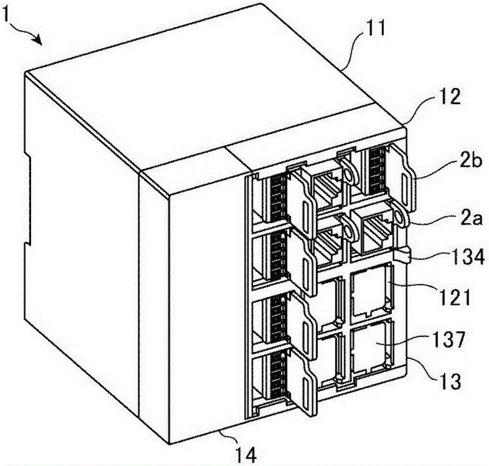
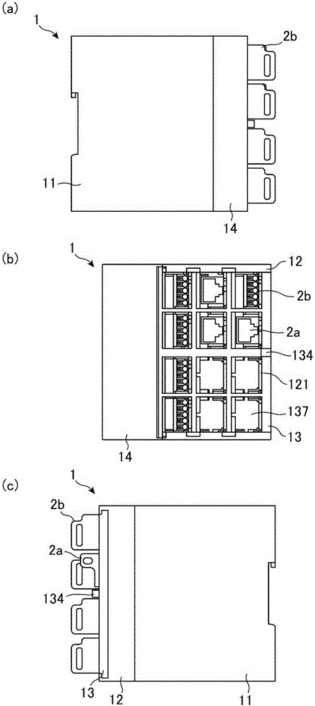
[0054] figure 1 , 2 It is a figure which shows the structural example of the board|substrate unit in Embodiment 1 of this invention.

[0055] Substrate unit such as figure 1 , 2 Shown is a unit in which substrates 2 are detachably stored in housing 1 , and substrate storage portions 121 are provided in a grid pattern to store substrates 2 in a plurality of rows and columns. Here, as a board unit, a regulator will be described as an example. In addition, the board|substrate storage part 121 should just be more than 2 rows and 2 columns, and in the example of a drawing, the case of 4 rows and 3 columns is shown.

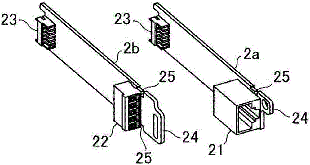
[0056] The substrate 2 is a part that realizes various functions of the regulator, such as image 3 constituted as shown. exist image 3 In the example shown in FIG. 1 , a board 2 a having a connector 21 connected to a LAN cable on one end side and a board 2 b having a terminal 22 connected to a terminal such as a heater on one end side are shown. The other end...


PUM


Abstract

In a circuit board unit storing circuit boards in a plurality of columns and rows, mounting and demounting of the circuit boards are locked without increasing an external shape of a product compared to a conventional configuration. Substrates (2) are provided that have cut-away portions (25) and a lock structure of a circuit board unit includes a slide portion (13) that is formed of a frame member having openings (131) arranged in a grid shape into which the circuit boards are able to be inserted and that is slidably mounted on a circuit board insertion surface of a front mask (12), and projection portions (135) that are provided in the slide portion (13) and are fitted into the cut-away portions (25) of the circuit boards (2) stored in a case (11) when the slide portion (13) is slid in one direction.

Description

technical field [0001] The present invention relates to a locking structure of a substrate unit in which a substrate is detachably accommodated in a storage case. Background technique [0002] In a panel meter or the like to which module parts can be added as customized, the substrate is fixed to the resin support portion by snap-fits, and the resin support portion is coupled to the frame by snap-fits. This snap is a method that is often used as one of the methods of joining two parts. [0003] On the other hand, when the substrate is made detachable, coupling by snapping is not suitable. That is, this is because when a snap is used as an attachment and detachment method, excessive load may be applied to the snap, which may cause breakage or fatigue fracture, thereby losing the coupling function. [0004] In contrast, conventionally, there is known a locking structure that locks attachment and detachment of a plurality of substrates housed in a row in a housing (for exampl...

Claims


Application Information

Patent Timeline
Patent Type & Authority Applications(China)
IPC IPC(8): H05K7/14
CPCH05K7/1417H05K7/1422H05K7/1408H05K5/0026H05K5/0252H05K5/03H05K7/14
Inventor 藤川刚生内海庆也
Owner YAMATAKE HONEYWELL CO LTD
Features
  • R&D
  • Intellectual Property
  • Life Sciences
  • Materials
  • Tech Scout
  • Unparalleled Data Quality
  • Higher Quality Content
  • 60% Fewer Hallucinations
Learn More