
Hydraulic rerailer

A rerailer and hydraulic technology, which is applied in the direction of railway auxiliary equipment, can solve the problems of low rescue efficiency and difficulty in lateral movement, and achieve the effect of improving rescue efficiency and facilitating rapid installation

Active Publication Date: 2016-12-14
王江山
View PDF7 Cites 0 Cited by
  • Summary
  • Abstract
  • Description
  • Claims
  • Application Information

AI Technical Summary

Problems solved by technology

[0003] The purpose of the present invention is to provide a hydraulic rerailer to solve the technical problems of difficult lateral movement and low rescue efficiency in the existing rerailer

Method used


Image

  • Hydraulic rerailer
  • Hydraulic rerailer
  • Hydraulic rerailer

Examples


Embodiment Construction

[0036] In order to make the purpose, technical solution and advantages of the present invention clearer, the technical solution of the present invention will be clearly and completely described below. Apparently, the described embodiments are only some of the embodiments of the present invention, but not all of them. Based on the embodiments of the present invention, all other embodiments obtained by persons of ordinary skill in the art without making creative efforts belong to the protection scope of the present invention.

[0037] In the description of the present invention, it should be noted that the orientation or positional relationship indicated by the terms "upper end", "lower end" and "top end" is based on the orientation or positional relationship shown in the drawings, and is only for the convenience of describing the present invention and Simplified descriptions, rather than indicating or implying that the device or element referred to must have a particular orient...


PUM


Abstract

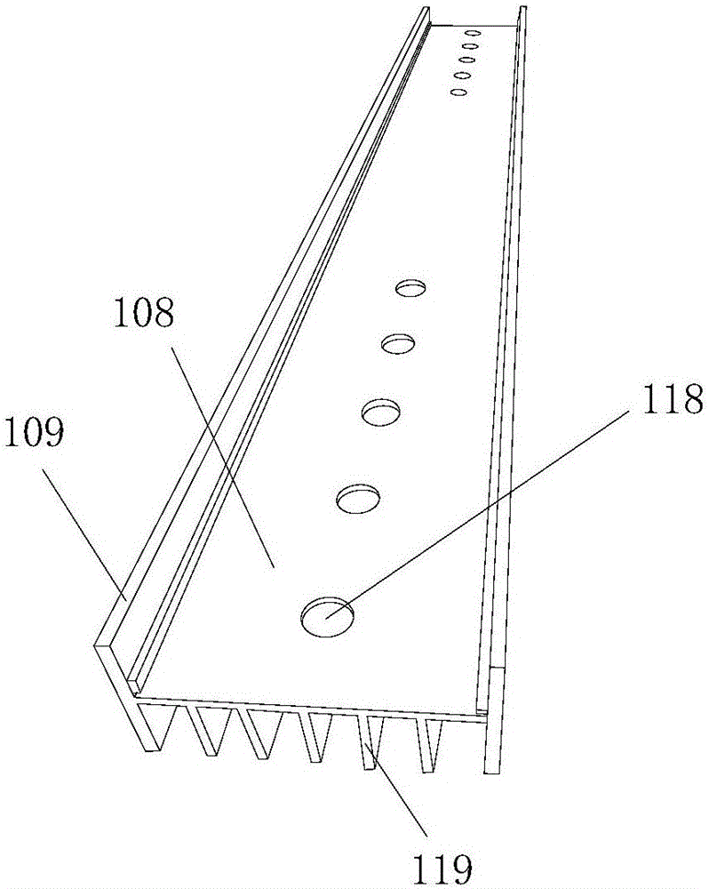
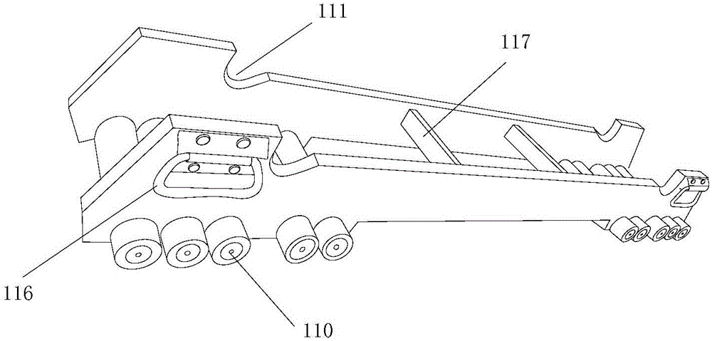
The invention belongs to the technical field of rerailing equipment and particularly relates to a hydraulic rerailer. The hydraulic rerailer comprises a transverse moving bridge, a transverse moving oil cylinder, a first oil cylinder, a second oil cylinder and a jack. The transverse moving bridge is provided with a base. Both the first oil cylinder and the second oil cylinder are located on the upper end face of the base. A cylinder body of the first oil cylinder and a cylinder body of the second oil cylinder are hinged to the base. A piston rod of the first oil cylinder and a piston rod of the second oil cylinder are both hinged to the jack and used for making the jack ascend or descend. A piston rod of the transverse moving oil cylinder is used for making the base move in the length direction of the transverse moving bridge. By the adoption of the hydraulic rerailer provided by the invention, a derailed car can be safely and stably jacked and moved transversely, fast on-site installation is facilitated, and the rescue efficiency is improved.

Description

technical field [0001] The invention belongs to the technical field of rerailing equipment, in particular to a hydraulic rerailing device. Background technique [0002] The train derailment accident is a vicious accident that destroys the normal order of rail transportation. After the accident, a safe and efficient rerailing equipment is needed to complete the rescue and recovery work. The installation process of the existing rerailer is complex, and there are disadvantages such as difficult lateral movement and low rescue efficiency. Therefore, it is urgent to provide a device suitable for rail transit such as subways, light rails or high-speed railways and capable of performing rapid rescue operations on derailed trains. the rerailer. Contents of the invention [0003] The object of the present invention is to provide a hydraulic rerailer to solve the technical problems of difficult lateral movement and low rescue efficiency existing in the existing rerailer. [0004] ...

Claims


Application Information

Patent Timeline
Patent Type & Authority Applications(China)
IPC IPC(8): B61K5/00
CPCB61K5/00
Inventor 王江山
Owner 王江山
Learn More