Fourth-order cumulant based co-prime array DOA (Direction of Arrival) angle estimation method

A direction of arrival and array technology, applied in the field of signal processing, can solve the problems of inability to estimate signals, waste of resources for reconnaissance and positioning, and the number of signals cannot meet the practical application, so as to achieve the effect of increasing the number of signal sources and improving the utilization rate of the array

Active Publication Date: 2016-12-14
XIDIAN UNIV
View PDF3 Cites 9 Cited by
  • Summary
  • Abstract
  • Description
  • Claims
  • Application Information

AI Technical Summary

Problems solved by technology

This method has the ability to estimate the number of signals that is more than the number of array elements, but the method still has the disadvantage that when the number of array elements is fixed, the number of signals that can be estimated sometimes still cannot meet the practical application
However, most of the existing angle-of-arrival estimation methods based on fourth-order cumulants are aimed at uniform arrays, a

Method used


Image

  • Fourth-order cumulant based co-prime array DOA (Direction of Arrival) angle estimation method
  • Fourth-order cumulant based co-prime array DOA (Direction of Arrival) angle estimation method
  • Fourth-order cumulant based co-prime array DOA (Direction of Arrival) angle estimation method

Examples


example 1

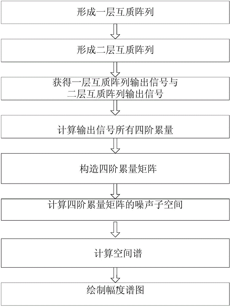
[0068] Simulation example 1. Construct a two-layer coprime array structure.

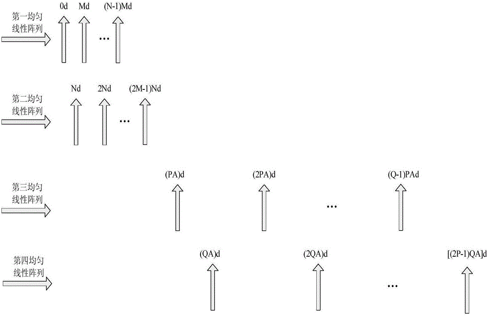
[0069] First, use the first uniform linear array a and the second uniform linear array b to form a coprime array, set N=2, M=3, the first uniform linear array a contains 3 elements, and the distance between the elements is 2d, The second uniform linear array b contains 3 array elements, and the array element spacing is 3d, and the first array element of the first uniform linear array a is placed at the 0d position;

[0070] Secondly, calculate the number of virtual array elements A=2MN+1=13 of a layer of coprime array formed by the first uniform linear array a and the second uniform linear array b;

[0071] Then, use the third uniform linear array c and the fourth uniform linear array f to form a two-layer coprime array, set P=2, Q=3, the third uniform linear array c contains 2 array elements, and the array element spacing is PA= 26d, the fourth uniform linear array f contains 3 array elements, the ...

example 2

[0074] In simulation example 2, all virtual array elements of a double-layer coprime array are calculated according to the fourth-order cumulant.

[0075] Assume that the element position of a layer of coprime array formed by the first uniform linear array a and the second uniform linear array b is [0, 2, 3, 4, 6, 9]d;

[0076] Let the positions of the two-layer coprime array elements formed by the third uniform linear array c and the fourth uniform linear array f be [26, 39, 52, 78, 117]d;

[0077] Calculate the virtual array formed by each array element of the first layer of coprime array and each array element of the second layer of coprime array as [26, 28, 29, 30, 32, 35]d, [39, 41, 42, 43,45,48]d, [52,54,55,56,58,61]d, [78,80,81,82,84,87]d, [117,119,120,121,123,126 ] d;

[0078] According to the method and principle of the fourth-order cumulant calculation, use the above-mentioned virtual arrays to generate all the final virtual array elements, and the results are show...


PUM


Abstract

The invention discloses a fourth-order cumulant based co-prime array DOA (Direction of Arrival) angle estimation method, which mainly solves problems in the prior art that the utilization rate of array elements is low and that the signal identification number is small. The estimation method comprises the implementation steps of 1) respectively building a one-layer co-prime array and a two-layer co-prime array; 2) acquiring an output signal of the one-layer co-prime array and an output signal of the two-layer co-prime array; 3) calculating all fourth-order cumulants according to the output signal of the one-layer co-prime array and the output signal of the two-layer co-prime array; 4) constructing a fourth-order cumulant array according to all of the fourth-order cumulants; 5) calculating a noise sub-space of the fourth-order cumulant array; 6) calculating a spatial spectrum according to the noise sub-space of the fourth-order cumulants and an array manifold matrix; and 7) drawing an amplitude spectrum according to the spatial spectrum, and acquiring a DOA angle. The estimation method disclosed by the invention greatly improves the recognizable source number of an array under the condition that the number of array elements is limited, and is applicable to target reconnaissance and passive location.

Description

technical field [0001] The invention belongs to the technical field of signal processing, in particular to a method for estimating the direction of arrival angle of array signals of electromagnetic signals, which can be used for reconnaissance and passive positioning of moving targets of aircraft and ships. Background technique [0002] Signal DOA estimation is an important branch in the field of array signal processing. It refers to the use of antenna arrays to inductively receive spatial acoustic signals and electromagnetic signals, and then use modern signal processing methods to quickly and accurately estimate the direction of the signal source. , has important application value in radar, sonar, wireless communication and other fields. With the continuous advancement of science and technology, there are higher and higher requirements for the degree of freedom that the array can achieve when estimating the signal direction of arrival. [0003] In the research on this pro...

Claims


Application Information

Patent Timeline
IPC IPC(8): G01S3/14G01S3/06
CPCG01S3/06G01S3/143
Inventor 蔡晶晶宗汝苏瑶刘高高李鹏
Owner XIDIAN UNIV
Why Eureka
Try Eureka