
Pole-side conductor sag observation method based on total station instrument

A wire sag, total station technology, applied in the direction of instruments, measuring devices, line-of-sight measurement, etc., can solve the problems of geographical limitation and complicated calculation, and achieve the effects of accurate results, simple operation and convenient calculation.

Inactive Publication Date: 2016-12-21
CHINA ELECTRIC POWER RES INST +2
View PDF4 Cites 18 Cited by
  • Summary
  • Abstract
  • Description
  • Claims
  • Application Information

AI Technical Summary

Benefits of technology

This technology uses an optical device called Total Station that has no extra tools needed for measurement purposes like ruler or calipers. It works with another instrument called LMU (laser distance meter). By measuring 3 different angles at once it allows us to determine how well this equipment's components are working correctly over time.

Problems solved by technology

This patented technical problem addressed during this patents describes how accurately detecting electrical sag (also known as sag) on high-voltage cables can be difficult due to various conditions like weather or other variables involved with cable installation. Existing techniques involve complicated calculation processes and require auxiliaries from time to perform these operations.

Method used


Image

  • Pole-side conductor sag observation method based on total station instrument

Examples


Embodiment Construction

[0030] The present invention will be further described below in conjunction with the accompanying drawings and specific embodiments, so that those skilled in the art can better understand the present invention and implement it, but the examples given are not intended to limit the present invention.

[0031] The total station type electronic speed measuring instrument is referred to as the total station instrument. It is a kind of horizontal angle, vertical angle measurement, slant distance, horizontal distance, height difference measurement and data processing. It is composed of mechanical, optical and electronic components. of measuring instruments. Because it only needs to be installed once, the instrument can complete all the measurement work on the station, so it is called "total station". At present, most total stations have the function of prism-free observation, which is not limited by the observation location, and the operation is simple. Accurate results and increased...


PUM


Abstract

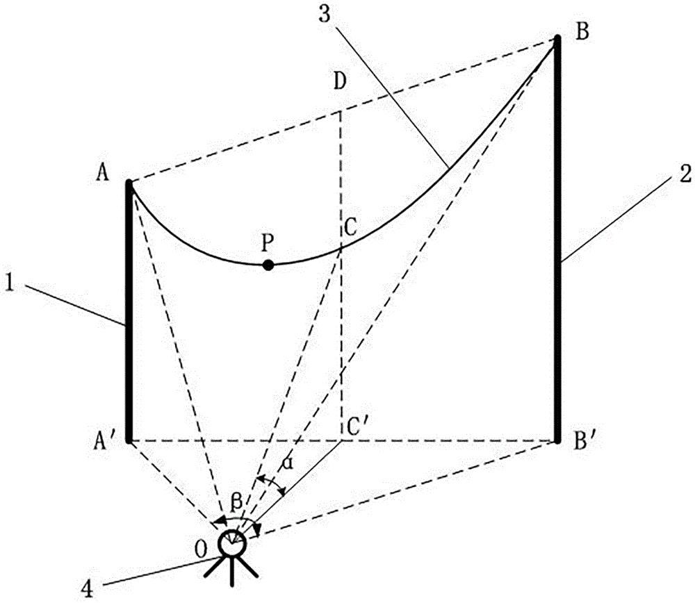
The invention discloses a pole-side conductor sag observation method based on a total station instrument, which is suitable for performing conductor sag observation at the external side of pole span of an electric transmission line with the total station instrument. The total station instrument is disposed at the external side of the pole span to respectively detect the altitude differences of a conductor wire at mount points on a first pole tower and a second pole tower by means of a prism-free function; by means of a planar triangle formed by the observation point and projections of the mount points on the two pole towers, first planar distance and second planar distance are measured; according to geometric principles, projective triangle interior angles and pole span length are calculated and further the position of midpoint of the pole span is determined; the length from the observation point to the midpoint of the pole span is calculated and is multiplied by the tangent value of elevation angle of the total station instrument to calculate the altitude difference of the conductor wire at the midpoint of the pole span; the average value of the first and the second altitude differences minus the altitude difference of the conductor wire at the midpoint of the pole span is finally calculated to obtain the conductor sag. Compared with a conventional conductor sag measurement method, the method allows optional site selection, has high precision and is simple in operations, and can be used in the fields of ultrahigh-voltage transmission line construction, overhead transmission line engineering construction, and measurement and control technologies and instruments and the like.

Description


Claims


Application Information

Patent Timeline
Owner CHINA ELECTRIC POWER RES INST
Learn More