Intelligent aerial survey flight exposure control method, unmanned aerial vehicle control method and terminal

A technology for exposure control and terminal control, applied in three-dimensional position/channel control, exposure control, non-electric variable control and other directions, it can solve the problems of insufficient image overlap and inability to adjust the exposure time interval, so as to ensure the overlap of routes and headings, The most efficient aerial survey and the effect of ensuring the quality of aerial survey

Active Publication Date: 2017-01-04
广州优飞信息科技有限公司
View PDF5 Cites 10 Cited by
  • Summary
  • Abstract
  • Description
  • Claims
  • Application Information

AI Technical Summary

Problems solved by technology

[0007] However, there are still technical defects in the existing technology: digital aerial cameras for professional surveying and mapping generally use fixed-point and equidistant exposures, and the exposure time interval cannot be adjusted according to changes in speed and altitude during the aerial photography process
It is easy to cause insufficient image overlap and poor image quality

Method used


Image

  • Intelligent aerial survey flight exposure control method, unmanned aerial vehicle control method and terminal
  • Intelligent aerial survey flight exposure control method, unmanned aerial vehicle control method and terminal
  • Intelligent aerial survey flight exposure control method, unmanned aerial vehicle control method and terminal

Examples


Embodiment 1

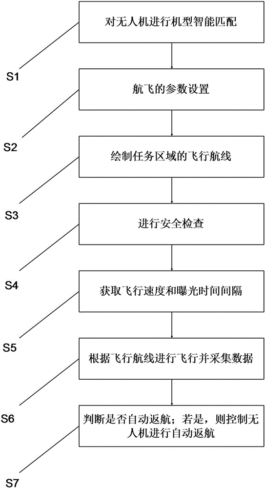
[0055] see figure 1 , which is a flow chart of the steps of the intelligent aerial survey flight exposure control method.

[0056] The invention provides an intelligent aerial survey flight exposure control method, comprising the following steps:

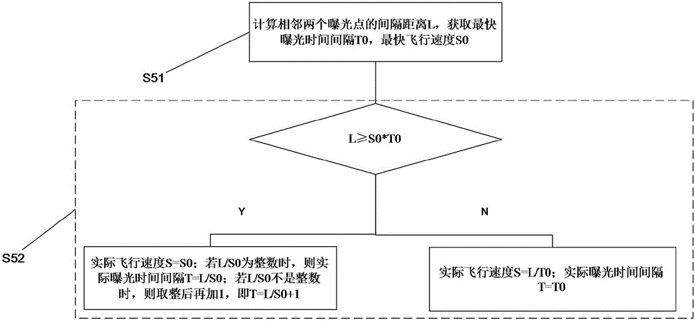
[0057] S51: Calculate the distance L between two adjacent exposure points, and obtain the fastest exposure time interval T0 and the fastest flight speed S0. Specifically, in this step, the separation distance L between two adjacent points is mainly calculated through the flight altitude, the degree of lateral overlap and the degree of heading overlap.

[0058] S52: If L≥S0*T0, then the actual flight speed S=S0; if L / S0 is an integer, then the actual exposure time interval T=L / S0; if L / S0 is not an integer, round up and add 1, namely T=L / S0+1;

[0059] If L

[0060] In the present invention, the speed and time interval during flight are calculated and co...

Embodiment 2

[0068] In addition, the present invention also applies the above-mentioned exposure control method to flight control. see image 3 , which is a flow chart of the flight control method of the unmanned aerial vehicle of the present invention. The present invention also provides a method for controlling the flight of an unmanned aerial vehicle, comprising the following steps:

[0069] S1: Intelligently match the model of the UAV.

[0070] Specifically, due to the large differences in hardware technical parameters of different types of UAV flight platforms (such as platform weight, flight time, maximum flight speed, wind resistance level, sensor exposure interval, memory card capacity, etc.), non-professional industries After the application personnel calculate and analyze a large number of parameters, it is quite complicated to ensure the safety of the flight and the quality of the task, which will greatly reduce the operation efficiency, and then affect the promotion and popul...


PUM


Abstract

The invention relates to an intelligent aerial survey flight exposure control method. The method comprises the following steps: S51: calculating the spacing distance L of two adjacent exposure points, and acquiring the smallest exposure time interval T0 and the highest flight speed S0; S52: if L being greater than or equal to S0*T0, the actual flight speed S being equal to S0; if L / S0 being an integer, the actual exposure time interval T being equal to L / S0; if L / S0 being not an integral, then adding 1 after the integral is obtained, namely T being equal to L / S0+1; and if L being smaller than S0*T0, the actual flight speed S being equal to L / T0, and the actual exposure time interval T being equal to T0. Moreover, the invention also provides an unmanned aerial vehicle control method and a control terminal using the method. Compared with the prior art, the exposure interval can be adjusted in real time, the forward overlap is guaranteed, and the aerial flight quality requirement is met.

Description

technical field [0001] The invention relates to the field of UAV control, in particular to an intelligent aerial survey flight exposure control method, a UAV control method and a terminal. Background technique [0002] In aerial photogrammetry, the exposure control device of aerial photogrammetry directly affects the quality of aerial photogrammetry results. Both the early film-type optical aerial photography and the later developed mainstream digital aerial photography are equipped with corresponding automatic exposure devices. When performing aerial survey tasks, since the optical aerial camera does not have a GPS positioning device, it mainly relies on an external timing exposure device to manually trigger the exposure. With the development of technology, the current mainstream digital aerial cameras are equipped with surveying GPS devices. In the planning stage of aerial survey missions, the precise coordinates of each exposure point on the route are calculated by the gr...

Claims


Application Information

Patent Timeline
IPC IPC(8): G03B7/00G05D1/10
CPCG03B7/00G05D1/101
Inventor 罗志勇熊勇良
Owner 广州优飞信息科技有限公司
Why Eureka
Try Eureka