
Layered fracture-matrix hybrid grid modeling method and device

A modeling method and grid technology, applied in 3D modeling, image data processing, special data processing applications, etc., can solve the problems of low degree of automation, inability to be simple, and rapid numerical simulation process.

Active Publication Date: 2017-01-11
CHINA PETROLEUM & CHEM CORP +1
View PDF3 Cites 10 Cited by
  • Summary
  • Abstract
  • Description
  • Claims
  • Application Information

AI Technical Summary

Problems solved by technology

Although the Corner Point Grid model (Corner PointGrid) widely used in geological modeling is easy to operate and the model is intuitive, it cannot describe the fracture network simply and accurately due to its structural hexahedral grid. Although the Discrete Fracture Model developed for fractured reservoirs can accurately describe the position and dip angle of each fracture
However, due to the use of unstructured tetrahedral grids for spatial division, the formation direction and the vertical formation direction are coupled with each other, and the vertical thickness of the formation is generally much smaller than the scale in the horizontal plane, which makes the discrete fracture model unable to guarantee the numerical simulation process at the same time. With faster speed and higher precision
In addition, the modeling process of the discrete fracture model is difficult and complex, with high uncertainty and low degree of automation

Method used


Image

  • Layered fracture-matrix hybrid grid modeling method and device
  • Layered fracture-matrix hybrid grid modeling method and device
  • Layered fracture-matrix hybrid grid modeling method and device

Examples


Embodiment Construction

[0020] Preferred embodiments of the present disclosure will be described in more detail below with reference to the accompanying drawings. Although preferred embodiments of the present disclosure are shown in the drawings, it should be understood that the present disclosure may be embodied in various forms and should not be limited to the embodiments set forth herein. Rather, these embodiments are provided so that this disclosure will be thorough and complete, and will fully convey the scope of the disclosure to those skilled in the art.

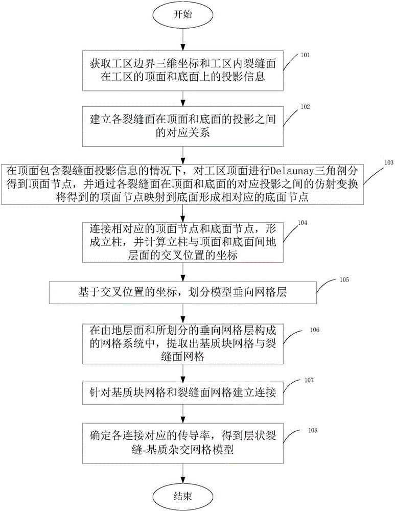
[0021] figure 1 A flow chart of a layered fracture-matrix hybrid grid modeling method according to an embodiment of the present invention is shown, the method includes:

[0022] Step 101: Obtain the three-dimensional coordinates of the boundary of the work area and the projection information of the fracture surface in the work area on the top and bottom surfaces of the work area;

[0023] Step 102, establishing the corresponding relationsh...


PUM


Abstract

The invention discloses a layered fracture-matrix hybrid grid modeling method and device. The method comprises the comprises of obtaining three-dimensional coordinates of work area boundaries and projection information of fracture surfaces on a top surface and a bottom surface in a work area, wherein the fracture surfaces are in the work area; establishing corresponding relationships among projections of the fracture surfaces on the top surface and the bottom surface; carrying out Delaunay triangulation on the top surface of the work area, thereby obtaining top nodes, and mapping the obtained top nodes to the bottom surface to form corresponding bottom nodes through affine transformation among corresponding projections of the crack surfaces on the top surface and bottom surface; connecting the corresponding top nodes and bottom nodes, thereby forming columns, and calculating coordinates of intersection positions of the columns and a stratum surface between the top surface and the bottom surface; dividing vertical grid layers of a model; a grid system composed of the stratum surface and the vertical grid layers, extracting matrix block grids and fracture surface grids, establishing connections for the matrix block grids and the fracture surface grids; and determining the conductivities corresponding the connections, thereby obtaining a layered fracture-matrix hybrid grid model.

Description

technical field [0001] The invention belongs to the field of geological modeling in oil exploitation technology, and more specifically relates to a layered fracture-matrix hybrid grid modeling method and device. Background technique [0002] The reserves of fractured oil reservoirs have exceeded half of the world's proven reserves at present, and the proven geological reserves of fractured oil reservoirs in my country exceed 40×108 tons, accounting for more than 28% of the total. According to the dip angle, fractures can be divided into vertical fractures, high-angle fractures, oblique fractures, and low-angle fractures. The reservoirs with vertical fractures and high-angle fractures are called high-angle fracture reservoirs. [0003] The geological modeling method and numerical simulation method of this kind of reservoir are the key technologies to optimize its development mode and enhance its oil recovery. Although the Corner Point Grid model (Corner PointGrid) widely use...

Claims


Application Information

Patent Timeline
Patent Type & Authority Applications(China)
IPC IPC(8): G06F17/50G06T17/05
Inventor 刘玄吕成远伦增珉赵淑霞何应付潘伟义周银邦张庆新廖海婴龚凯
Owner CHINA PETROLEUM & CHEM CORP
Learn More