electrical connector

An electrical connector and power supply technology, which is applied in the direction of connection and connection device components and circuits, can solve the problems of overheating and temperature rise of mobile phones, and achieve the effect of increasing the heat dissipation surface and improving the heat dissipation performance.

Active Publication Date: 2018-09-11
LINKCONN ELECTRONICS
View PDF1 Cites 0 Cited by
  • Summary
  • Abstract
  • Description
  • Claims
  • Application Information

AI Technical Summary

Problems solved by technology

[0006] The technical problem to be solved by the present invention is to provide an electrical connector, which solves the problem that the temperature rise of the product is too high when the current is high, and the user feedbacks that the mobile phone is hot when charging

Method used


Image

  • electrical connector
  • electrical connector
  • electrical connector

Examples


Embodiment Construction

[0029] The present invention will be further described below in conjunction with the drawings and embodiments.

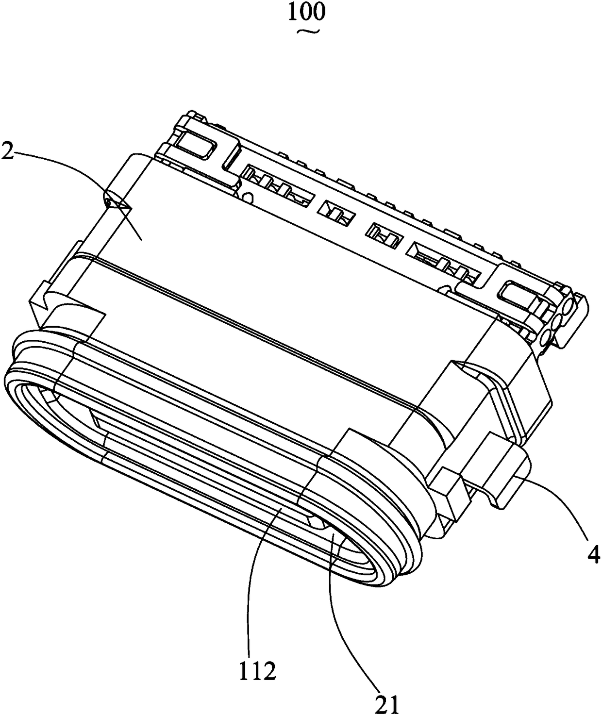
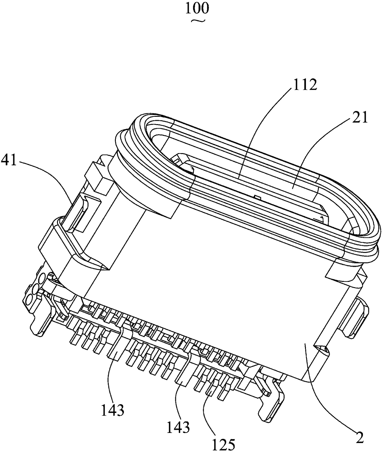
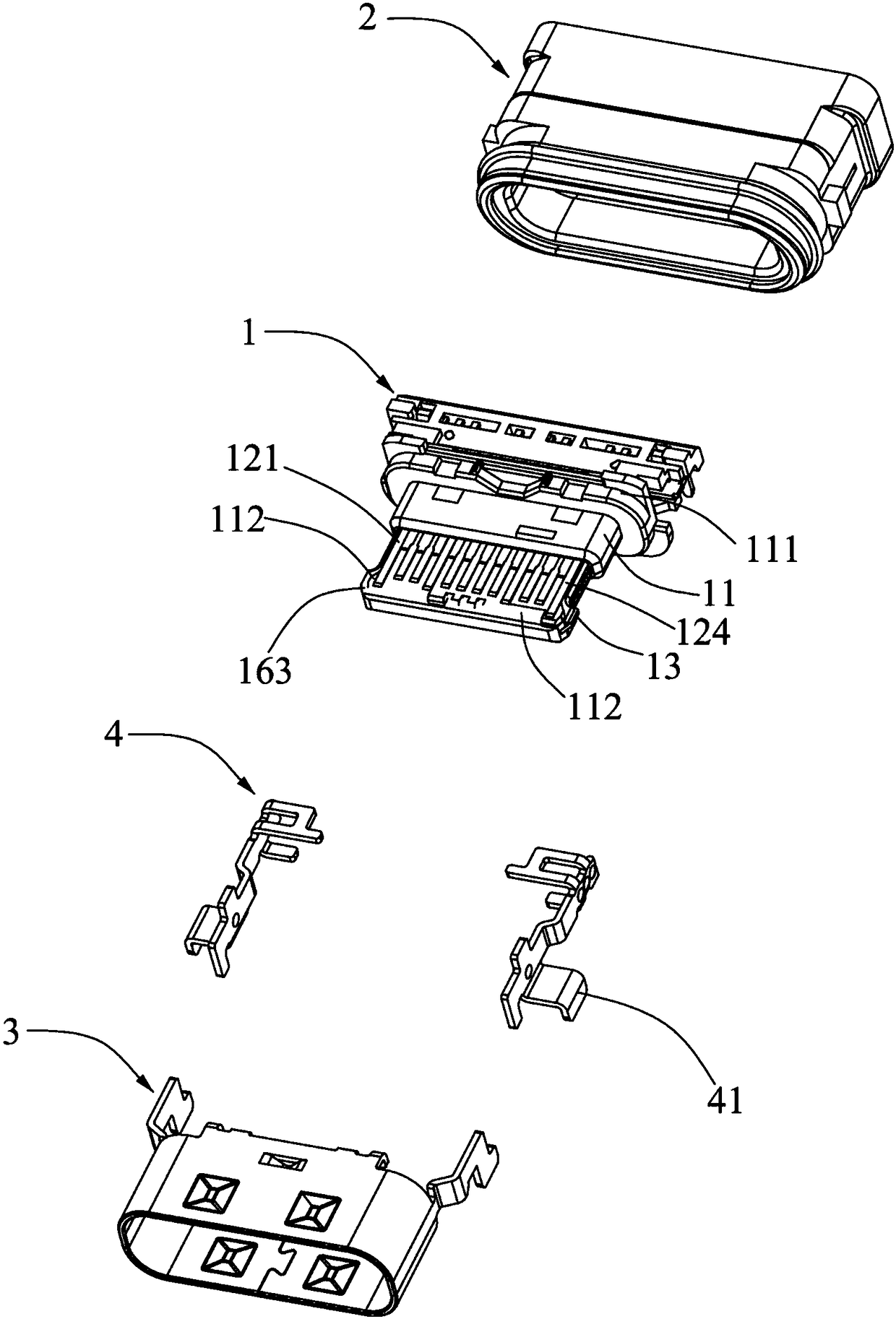
[0030] Such as Figure 1 to Figure 9 As shown, an electrical connector 100 according to the present invention includes a terminal module 1, a plastic shell 2, a main iron shell 3, and a secondary iron shell 4.

[0031] The terminal module 1 includes an insulating body 11, a plurality of conductive terminals 12 fixed to the insulating body 11, a pair of lock shielding pieces 13 embedded in the insulating body 11, and a power terminal assembly 14. The insulating body 11 includes a base 111 and a tongue 112 extending forward from the base 111. The plurality of conductive terminals 12 includes a row of upper terminals 121 and a row of lower terminals 122. A row of upper terminals 121 includes signal terminals and ground terminals, and a row of lower terminals 122 includes signal terminals and ground terminals. Of course, the number of upper terminals 121 in a row and the n...


PUM


Abstract

The invention discloses an electric connector. The electric connector comprises an insulation body and a plurality of conductive terminals. The insulation body comprises a base portion and a tongue plate extending forwards from the base portion. The conductive terminals include a row of upper terminals and a row of lower terminals. Each upper terminal comprises an upper fixing portion embedded into the insulation body, an upper contact portion exposed out of the upper surface of the tongue plate and an upper welding portion extending out of the base portion. Each lower terminal comprises a lower fixing portion embedded inside the insulation body, a lower contact portion exposed out of the lower surface of the tongue plate, and a lower welding portion extending out of the base portion. The electric connector further comprises a power supply terminal assembly piece. The power supply terminal assembly piece comprises four power supply contact portions exposed out of the upper and lower surfaces of the tongue plate, a slab portion connected with the four contact portions and a power supply welding portion extending out of the base portion. According to the electric connector, integration of the four power supply terminals can be achieved, and therefore a radiating surface can be increased.

Description

Technical field [0001] The invention relates to an electrical connector, in particular to an electrical connector for high current. Background technique [0002] The USB Association announced a USB Type-C electrical connector on June 23, 2013. The highlight of this USB Type-C electrical connector is a slimmer design and support for double-sided insertion of the USB interface. This formally solves the problem of "USB The global problem of "forever inaccurate" is inserted casually. [0003] The current-carrying terminals of the existing USB Type-C products are the power terminal and the ground terminal; the ground terminal can indirectly increase the heat dissipation surface through the structural design of connecting the middle shielding sheet and the outer iron shell. However, due to the requirements of the Association's specifications, the contact surface of the male and female terminals of the product is limited by the width of 0.25mm and the circuit layout requirements. The pow...

Claims


Application Information

Patent Timeline
Patent Type & Authority Patents(China)
IPC IPC(8): H01R13/02H01R13/648H01R13/658H01R13/40H01R13/502H05K7/20
CPCH01R13/02H01R13/40H01R13/502H01R13/648H01R13/658H05K7/20
Inventor 王财源姚涛
Owner LINKCONN ELECTRONICS
Why Eureka
Try Eureka