Dimming driving circuit

A dimming drive and circuit technology, applied in the direction of lamp circuit layout, light source, electric light source, etc.

Active Publication Date: 2017-01-25
SHANGHAI SIMAX TECH CO LTD
View PDF5 Cites 4 Cited by
  • Summary
  • Abstract
  • Description
  • Claims
  • Application Information

AI Technical Summary

Problems solved by technology

But unfortunately, the existing technology rarely provides a driving scheme based on the use of TRIAC dimmers to adjust the lighting intensity of LED devices efficiently and instantaneously.

Method used


Image

  • Dimming driving circuit
  • Dimming driving circuit
  • Dimming driving circuit

Examples


Embodiment Construction

[0029]Below in conjunction with each embodiment, the technical solution of the present invention is clearly and completely set forth, but described embodiment is only the embodiment that the present invention is used for describing description and not all embodiments, based on these embodiments, this invention The solutions obtained by those skilled in the art without creative work all belong to the protection scope of the present invention.

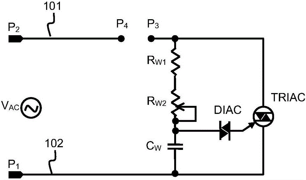
[0030] The bidirectional thyristor commonly used in dimmers used in the lighting field is usually called TRIAC in the industry, and is mainly operated as a three-pole AC switch (TRI-ELECTRODE AC SWITCH), and its customary term is called a bidirectional thyristor or a bidirectional thyristor. switch. see Figure 1A , in the thyristor dimmer, as long as an appropriate trigger pulse is applied to the control electrode of the bidirectional thyristor TRIAC, no matter the AC voltage V input on the input lines 101, 102 AC Whether the positive ...


PUM


Abstract

The invention mainly relates to the field of driving of luminescent devices, and provides a dimming driving circuit for driving LED in a voltage conversion power supply system based on alternating current electric supply and a dimming method. Duty ratio of a PMW driving signal is linearly changed along with change of phase corner cut of alternating current. A dimming unit is used for detecting change conditions of a conduction angle of the alternating current, and meanwhile, the duty ratio of a modulating signal is further controlled to be changed along with trend of degree change of the conduction angle.

Description

technical field [0001] The present invention mainly relates to the field of driving light-emitting devices, more precisely, it is a dimming drive circuit and a dimming method for driving LEDs in a voltage conversion power supply system based on AC mains, which can realize the duty cycle of the PWM drive signal It changes linearly with the change of the AC phase cutting angle. Background technique [0002] With the increasingly severe global energy and environmental resource problems, with the advantages of energy saving, environmental protection, safety and reliability, the white LED of the solid-state light source is gradually becoming the engine of green lighting. Along with it, the driving power supply has become extremely important in the LED lighting industry chain. In the link, the drive power supply is constantly developing towards high efficiency and low power consumption, taking into account safety, environmental protection and low cost. At the same time, we also n...

Claims


Application Information

Patent Timeline
Patent Type & Authority Applications(China)
IPC IPC(8): H05B37/02
Inventor 许明伟高智浩
Owner SHANGHAI SIMAX TECH CO LTD
Why Eureka
Try Eureka