Automatic centering device

A technology of automatic centering and height adjustment device, applied in the direction of measuring device, mechanical device, mechanical measuring device, etc., can solve the problems of inaccuracy of measurement results, inaccurate data results, uneven force on wheels, etc. Improve work efficiency and measurement accuracy, data results are true and accurate, and avoid accidental damage

Inactive Publication Date: 2017-02-01
NANJING WOYU MECHANICAL & ELECTRICAL EQUIP CO LTD
View PDF4 Cites 7 Cited by
  • Summary
  • Abstract
  • Description
  • Claims
  • Application Information

AI Technical Summary

Problems solved by technology

[0002] The thrust line is an imaginary line extending forward from the center of the rear axle of the car, and the direction of travel of the rear axle is jointly determined by the rear wheels on both sides of the car. The thrust angle is the angle between the longitudinal axis of the car in the top view plane and the thrust line , the thrust line deviates to the left relative to the longitudinal axis of the car is positive, and the deviation to the right is negative. If the rear wheels point to the front and the thrust line is consistent with the longitudinal axis of the car, the thrust angle is zero. At this time, the car When driving in a straight line, the rear-wheel drive car moves forward along the thrust line and the longitudinal axis of the car, so zero thrust angle is ideal; if the rear wheels are not pointing straight ahead, the thrust line is inconsistent with the longitudinal axis of the car, and the thrust angle is not equal to zero. At this time, the rear-wheel-drive car moves forward along the thrust line, forming a certain angle with the longitudinal axis of the car. Driving in this state will cause accelerated tire wear or deviation, which will greatly increase the fuel consumption of the car, even when the car is fully loaded. In the process, a tire blows out, causing danger and causing economic losses; at the same time, if the longitudinal axis of the vehicle is in the same direction as the thrust line of the vehicle, but the longitudinal axis of the vehicle and the thrust line of the vehicle do not coincide together, that is, the central axis of the frame beam of the vehicle and the rear axis of the vehicle The vertical intersection point of the central axis of the bridge is not at the center point of the rear axle of the car, resulting in uneven force on the wheels at both ends of the rear axle of the car, which will also cause accelerated wear or deviation of the tires and greatly increase the fuel consumption of the car, even when the car is fully loaded. A tire blowout occurs in the middle of the road, causing danger and causing economic losses
[0003] At present, when domestic automobile manufacturers and automobile repair centers measure whether the longitudinal axis of the automobile and the thrust line of the automobile coincide, that is, whether the vertical intersection point of the central axis of the automobile frame beam and the central axis of the rear axle of the automobile is measured is not on the rear axle of the automobile. When the center point is on, the accuracy of the measurement results is not high. The main reason for this situation is that the error is large when determining the center point of the rear axle of the car. The existing method of mainly determining the center point of the rear axle of the car is through manual operation. Use a ruler to measure the distance between the hubs of the rear axle of the car, and then determine the center point of the rear axle of the car. The center point of the rear axle will have a greater error, which will eventually lead to untrue and accurate data results of other subsequent measurement work

Method used


Image

  • Automatic centering device
  • Automatic centering device
  • Automatic centering device

Examples


Embodiment Construction

[0026] The present invention will be described in detail below in conjunction with the accompanying drawings.

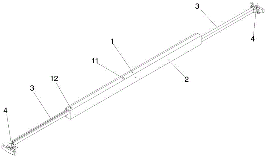
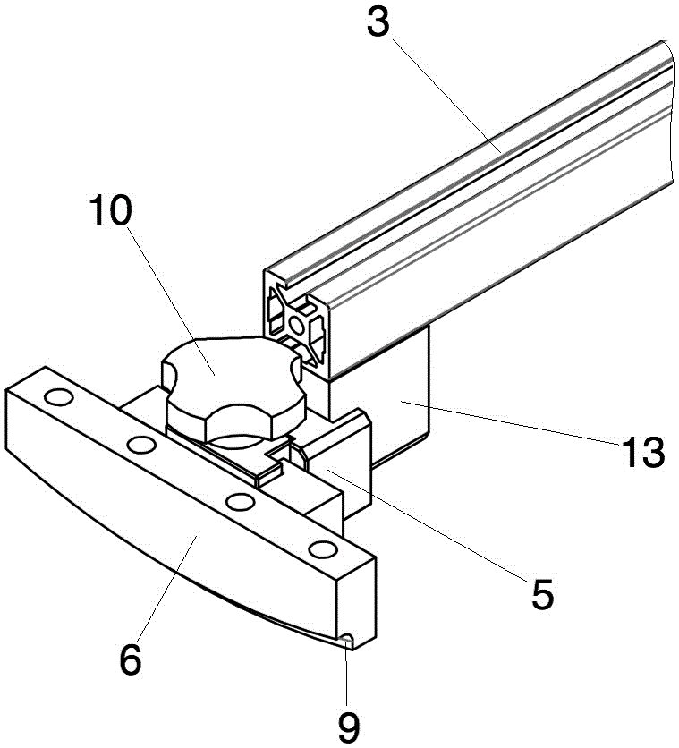
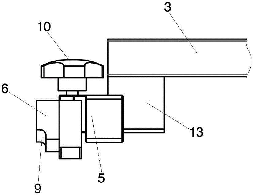
[0027] Such as figure 1 and 6 As shown: this embodiment is an automatic centering device, including a telescopic body 2 provided with a central point 1, and two telescopic rods 3 are arranged inside the telescopic body 2, and the two telescopic rods 3 are connected from two ends of the telescopic body 2 respectively. Both ends extend outward or contract inward at the same time, and the stroke lengths of the two telescopic rods 3 when extending outward or contracting inward are equal, such as Figure 2-4 As shown: a hub connection mechanism 4 is provided on the end of the telescopic rod 3, and the hub connection mechanism 4 includes a height adjustment device 5 that is slidingly connected to the end of the telescopic rod 3 and is arranged on the outer surface of the height adjustment device 5 and contacts with the wheel hub. Connected hub positioning block 6; in ord...


PUM


Abstract

The invention discloses an automatic centering device comprising a telescopic body having a center point. Two expansion rods are arranged inside the telescopic body and extend outwardly or contract inwardly simultaneously from the two ends of the telescopic body, wherein the travel lengths of outward extending and inward contraction of the two expansion rods are equal. Besides, hub connecting mechanisms are arranged at the ends of the expansion rods and include height adjusting devices in sliding connection with the ends of the expansion rods and hub positioning blocks that are arranged at the outer side surfaces of the height adjusting devices and are in contact connection with the wheel hubs. According to the invention, the automatic centering device having a simple structure can be operated conveniently; the central point of a rear axle of an automobile can be determined precisely; the work efficiency and measurement accuracy are improved; data results of other follow-up work can be guaranteed to be real and accurate.

Description

technical field [0001] The invention relates to a fixture for determining the center point between two wheels of an automobile rear axle, in particular to an automatic centering device, which belongs to the technical field of automobiles. Background technique [0002] The thrust line is an imaginary line extending forward from the center of the rear axle of the car, and the direction of travel of the rear axle is jointly determined by the rear wheels on both sides of the car. The thrust angle is the angle between the longitudinal axis of the car in the top view plane and the thrust line , the thrust line deviates to the left relative to the longitudinal axis of the car is positive, and the deviation to the right is negative. If the rear wheels point to the front and the thrust line is consistent with the longitudinal axis of the car, the thrust angle is zero. At this time, the car When driving in a straight line, the rear-wheel drive car moves forward along the thrust line a...

Claims


Application Information

Patent Timeline
Patent Type & Authority Applications(China)
IPC IPC(8): G01B5/00
CPCG01B5/0025
Inventor 郑明誉
Owner NANJING WOYU MECHANICAL & ELECTRICAL EQUIP CO LTD
Why Eureka
Try Eureka