
A high-frequency gas excitation tester

A tester and gas technology, applied in the field of high-frequency gas excitation tester, can solve the problems of high drive motor power, high test cost, and no technical solution, and achieve the effect of low power demand and wide excitation frequency range

Active Publication Date: 2019-02-05
AECC SHENYANG ENGINE RES INST
View PDF7 Cites 0 Cited by
  • Summary
  • Abstract
  • Description
  • Claims
  • Application Information

AI Technical Summary

Problems solved by technology

[0002] The vibration characteristics test of aeroengine blades is usually excited by an electromagnetic vibration table, and the frequency is not higher than 5000 Hz. It is powerless for the test of the integration of the integral blisk or the integral blade ring of a certain model. An electromagnetic vibration table is required for the excitation frequency exceeding 5000 Hz. It is difficult to achieve, even if the excitation over 5000Hz can be realized, the excitation energy is usually very small, and there is no technical solution for the excitation of the entire blade.
[0003] For the integral blisk and leaf ring technology widely used in a certain model, foreign countries have begun to study the whole-stage blade excitation method based on the rotor tester. Usually, a high-speed gas or liquid excitation nozzle with a stator is used. The high-frequency excitation obtained by this method The frequency can reach more than 10,000 Hz, but the power of the driving motor is high, and it is carried out in a vacuum box. The test box needs to be vacuumed, and the test cost is relatively high. The safety of the test piece cannot be guaranteed under high-speed rotation.

Method used


Image

  • A high-frequency gas excitation tester
  • A high-frequency gas excitation tester
  • A high-frequency gas excitation tester

Examples


Embodiment Construction

[0019] In order to make the objectives, technical solutions and advantages of the present invention clearer, the technical solutions in the embodiments of the present invention will be described in more detail below in conjunction with the drawings in the embodiments of the present invention. In the drawings, the same or similar reference numerals denote the same or similar elements or elements having the same or similar functions throughout. The described embodiments are some, but not all, embodiments of the invention. The embodiments described below by referring to the figures are exemplary and are intended to explain the present invention and should not be construed as limiting the present invention. Based on the embodiments of the present invention, all other embodiments obtained by persons of ordinary skill in the art without creative efforts fall within the protection scope of the present invention. Embodiments of the present invention will be described in detail below ...


PUM


Abstract

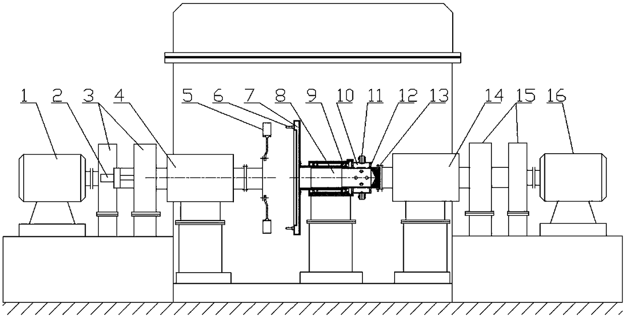
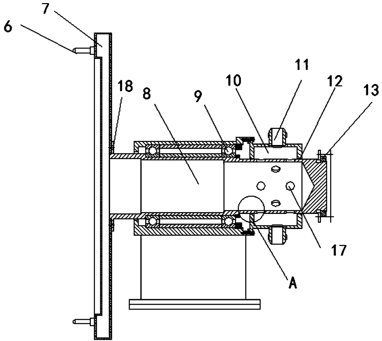
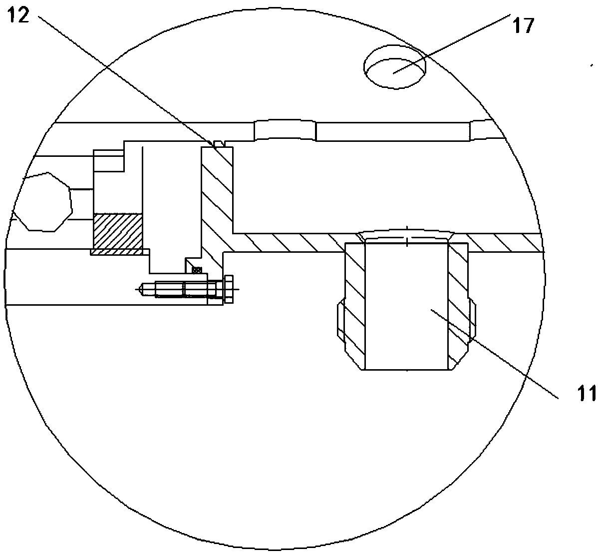
The invention discloses a high frequency gas excitation tester, which belongs to the technical field of engine blade experiment. In the present invention, the first motor drives the first double fulcrum driving shaft through the first speed increaser to drive a to-be-tested overall blade plate. The second motor drives the second double fulcrum driving shaft through the second speed increaser; the second double fulcrum driving shaft, through soft connection, is connected to an air guiding shaft positioned by the double positioning fulcrum; the air guiding shaft seals the gas collection ring through a well-sealing flange; the gas collection ring is provided with an excitation spray nozzle at the position corresponding to the blade of the blade plate. The air guiding ring fixedly arranged on the double positioning fulcrum guides air in through the air inlet nozzle. Between the air guiding ring and the air guiding shaft, a well-sealing tooth is provided to have the two sealed. The air guiding shaft is provided with an air guiding hole. The air enters the air guiding shaft from the air guiding ring through the air guiding hole, and arrives at the excitation nozzle through the air collection ring before finally being exerted on the blade of the blade plate to perform real time testing on vibration response of the to-be-tested blade through electric guiding device. The excitation frequency range of the invention is wide; the excitation energy can be adjusted; and the whole-stage blade can be tested synchronously.

Description

technical field [0001] The invention belongs to the technical field of engine blade experiments, and in particular relates to a high-frequency gas excitation tester. Background technique [0002] The vibration characteristics test of aeroengine blades is usually excited by an electromagnetic vibration table, and the frequency is not higher than 5000 Hz. It is powerless for the test of the integration of the integral blisk or the integral blade ring of a certain model. An electromagnetic vibration table is required for the excitation frequency exceeding 5000 Hz. It is very difficult to achieve, even if the excitation exceeding 5000Hz can be realized, the excitation energy is usually very small, and there is no technical solution to realize the excitation of the entire blade. [0003] For the integral blisk and leaf ring technology widely used in a certain model, foreign countries have begun to study the whole-stage blade excitation method based on the rotor tester. Usually, a...

Claims


Application Information

Patent Timeline
Patent Type & Authority Patents(China)
IPC IPC(8): G01M7/02
CPCG01M7/022
Inventor 李成刚刘俊峰李铁宁智轶
Owner AECC SHENYANG ENGINE RES INST
Learn More