Automatic clipping device for server cabinet frame supporting rod

A technology for server cabinets and support rods, which is applied in the direction of shearing devices, attachments of shearing machines, knives for shearing machines, etc., and can solve problems such as low work efficiency

Active Publication Date: 2017-02-08
EASTERN LIAONING UNIV
View PDF7 Cites 2 Cited by
  • Summary
  • Abstract
  • Description
  • Claims
  • Application Information

AI Technical Summary

Problems solved by technology

Different server cabinets require different lengths of support rods, and when making the internal frame of a server cabinet of the same specification, more bar-shaped support rods of the same specification are needed, because the bar-shaped support rods are formed from a longer bar-shaped The support rod is cut according to the size to meet the needs of the server cabinet. Therefore, it needs to be measured and cut many times, and the work efficiency is low.

Method used


Image

  • Automatic clipping device for server cabinet frame supporting rod
  • Automatic clipping device for server cabinet frame supporting rod
  • Automatic clipping device for server cabinet frame supporting rod

Examples


Embodiment Construction

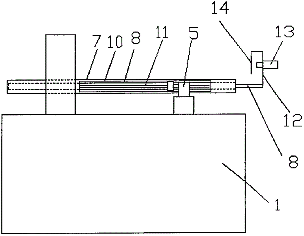
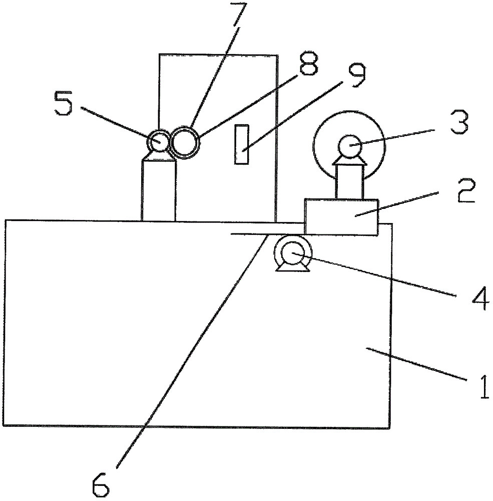
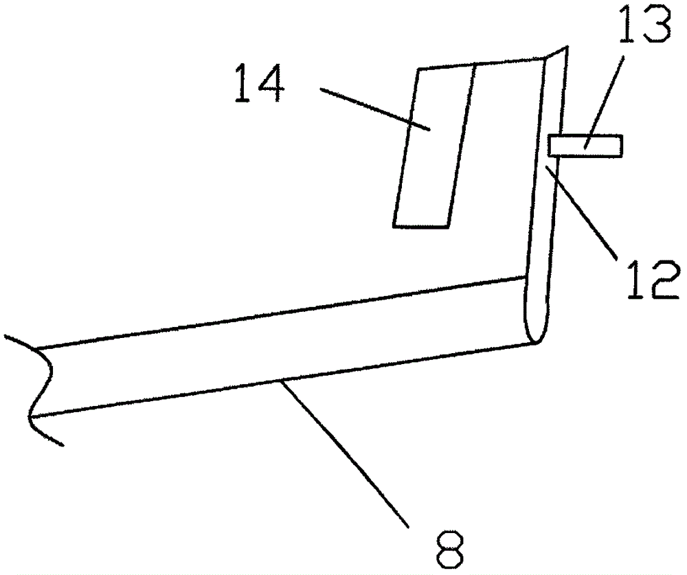
[0017] combine figure 1 , 2 , 3, an automatic cutting device for server cabinet frame support rods of the present invention includes a base, a positioning rod, a motor, a cutter seat, a cutter, a processor and a travel switch.

[0018] The positioning rod includes an outer rod and an inner rod. The inner rod is sleeved outside the outer rod and the two are arranged coaxially. There is a bearing inside the outer rod. The inner rod is connected to the outer rod through the bearing. The inner rod can rotate relative to the outer rod but cannot move axially. .

[0019] The inner rod is a stepped rod, the outer diameter of the largest part of the outer diameter of the inner rod matches the inner diameter of the outer rod, and the outer rod has an axially extending slit hole, and the outer circumference of the largest part of the inner rod is evenly provided with a ring around the inner rod. The teeth distributed on the central axis of the rod, and the teeth are exposed in the hol...


PUM


Abstract

The invention discloses an automatic clipping device for a server cabinet frame supporting rod. The automatic clipping device comprises a base, a positioning rod, a motor, a cutter base, a cutter, a processor and a travel switch. The positioning rod comprises an outer rod body and an inner rod body. The inner rod body is arranged at the outer portion of the outer rod body in a sleeving manner, and the inner rod body and the outer rod body are coaxially arranged. The inner rod body can rotate relative to the outer rod body but cannot axially move. The outer rod body is provided with a notch hole extending in the axial direction. Teeth distributed around a center axis of the inner rod body are evenly arranged on the outer circumference of the inner rod body. The base is provided with a positioning rod clamping hole and a fastening device, the base is provided with motors, and the motors include the first motor, the second motor and the third motor. The travel switch is used for detecting whether the supporting rod is fed in place or not and sending signals to the processor. Instructions are sent to the first motor, the second motor and the third motor through the processor, the first motor is made to drive the cutter to conduct cutting, the second motor drives the cutter base to move, the third motor drives the inner rod body to rotate, accordingly, automatic clipping and automatic discharging on the supporting rod are achieved, and the work efficiency is improved.

Description

technical field [0001] The invention relates to an automatic cutting device for a support rod of a server cabinet frame, belonging to the field of cutting equipment. Background technique [0002] When making a server cabinet, since the internal space of the server cabinet needs to be divided into different placement areas by a frame, the frame is formed of strip support rods. Different server cabinets require different lengths of support rods, and when making the internal frame of a server cabinet of the same specification, more bar-shaped support rods of the same specification are needed, because the bar-shaped support rods are formed from a longer bar-shaped The support rods are cut according to the size to meet the needs of the server cabinet. Therefore, many times of measuring and cutting are required, and the work efficiency is low. [0003] In view of this, the present invention is proposed. Contents of the invention [0004] The technical problem to be solved by t...

Claims


Application Information

Patent Timeline
Patent Type & Authority Applications(China)
IPC IPC(8): B23D19/00B23D33/02B23D35/00
CPCB23D19/00B23D33/02B23D35/004
Inventor 张晓光高友
Owner EASTERN LIAONING UNIV
Why Eureka
Try Eureka