Automatic drilling device for sphygmomanometer case

A drilling device and sphygmomanometer technology, applied in boring/drilling, drilling/drilling equipment, metal processing equipment, etc., can solve the problems of high labor intensity, low processing efficiency, affecting processing accuracy, etc. Avoid disassembly and re-clamping, improve production efficiency, suitable for mass production results

Active Publication Date: 2018-08-14
来安县永阳知识产权运营有限公司
View PDF10 Cites 0 Cited by
  • Summary
  • Abstract
  • Description
  • Claims
  • Application Information

AI Technical Summary

Problems solved by technology

[0003] In view of the above problems, the present invention provides an automatic drilling device for the case of the sphygmomanometer, which can solve the problem of low processing efficiency and repeated clamping of the workpiece when the existing processing method is used to process the through hole on the boss of the sphygmomanometer case. It is easy to affect the processing accuracy, and the labor intensity of workers is also very high.

Method used


Image

  • Automatic drilling device for sphygmomanometer case
  • Automatic drilling device for sphygmomanometer case
  • Automatic drilling device for sphygmomanometer case

Examples


Embodiment Construction

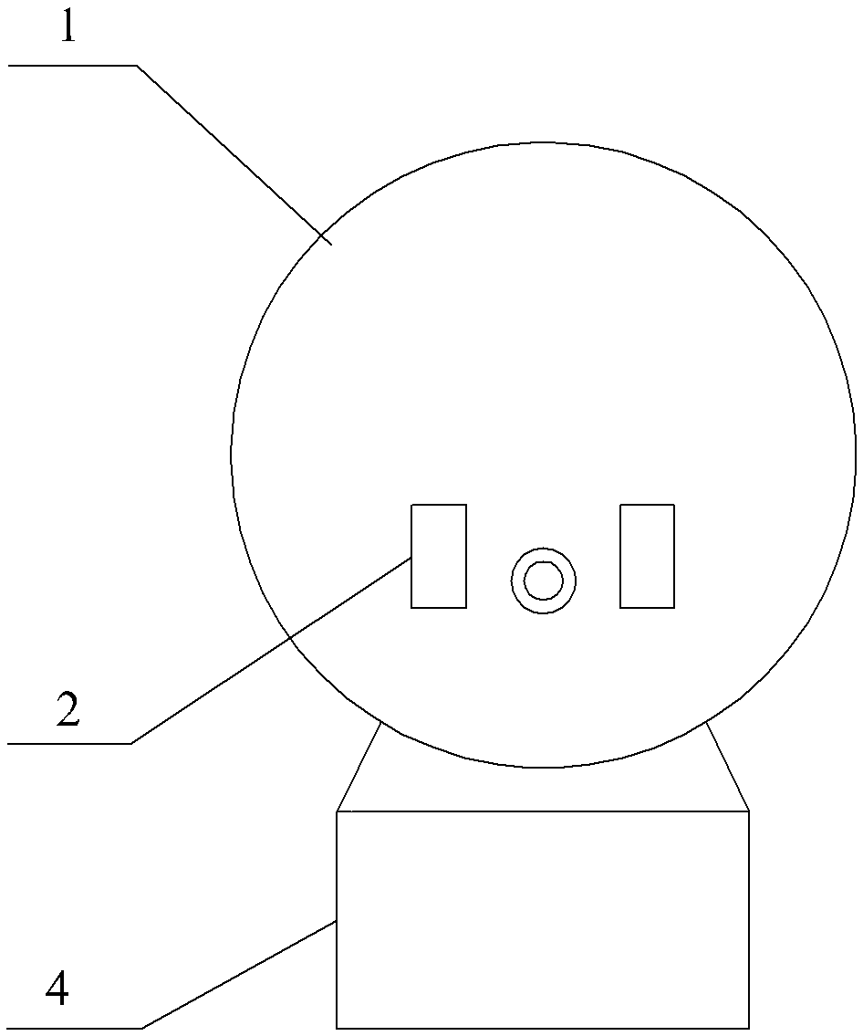
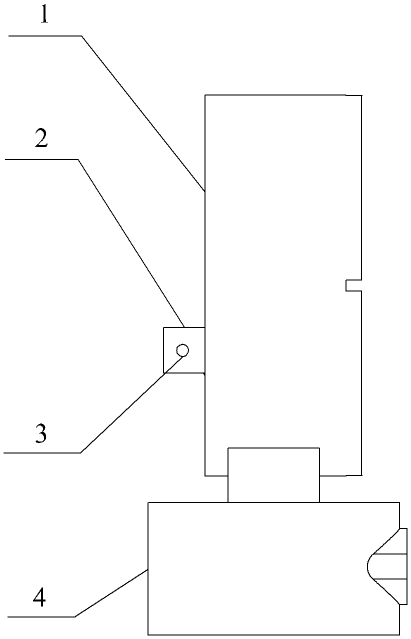
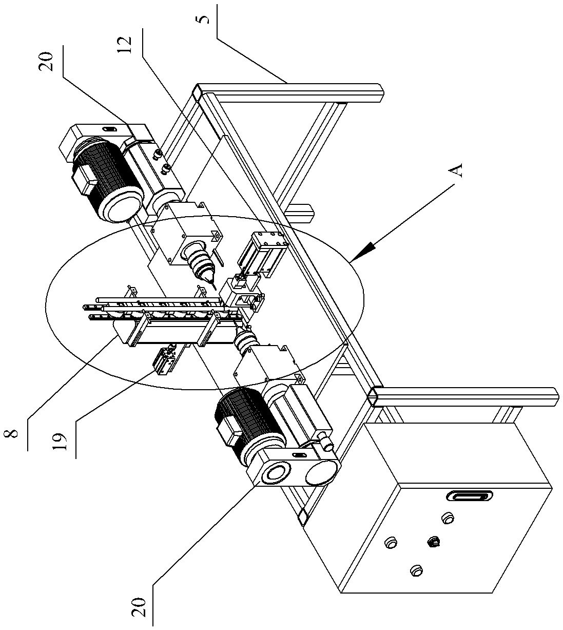
[0017] See Figure 1-7 , a kind of sphygmomanometer case automatic drilling device of the present invention, it comprises frame 5, two drilling machines 20 and PLC control system, the top surface of frame 5 is fixedly connected with support 8, and the front end of support 8 is provided with Vertically arranged workpiece limiting groove, the upper end and the lower end of the workpiece limiting groove are respectively the workpiece inlet and the workpiece outlet. Slide and leave the workpiece limit groove from the workpiece outlet; image 3 Six sphygmomanometer watch cases can be accommodated in the workpiece limiting groove at the same time.

[0018] A guide support frame 11 and a first cylinder fixing bracket 12 are installed in sequence on the frame 5 directly in front of the workpiece limiting groove, and the first cylinder fixing bracket 12 is equipped with a first cylinder 13 and a second cylinder 14 arranged up and down. The first cylinder 13 and the second cylinder 14...


PUM


Abstract

The invention provides a sphygmomanometer shell automatic drilling device, which can solve the problems of low machining efficiency in machining of a through hole in a sphygmomanometer shell boss by a traditional machining mode, easy influence on the machining precision by repeated workpiece clamping and higher labor intensity of workers. The sphygmomanometer shell automatic drilling device comprises a frame, drilling machines and a PLC control system; the top surface of the frame is fixedly connected with a bracket; a workpiece limiting groove is vertically formed in the front end of the bracket; a first cylinder and a second cylinder are mounted on a first cylinder fixed bracket; the front end of a piston rod of the first cylinder is fixedly connected with a positioning block; the front end of a piston rod of the second cylinder is fixedly connected with a support plate; a guide support frame is provided with an induction switch aligned to a sphygmomanometer shell at the lowermost side of the workpiece limiting groove; and the drilling machines are mounted on the frame, and are respectively positioned on the left and right two sides of the bracket.

Description

technical field [0001] The invention relates to the technical field of drilling tooling, in particular to an automatic drilling device for a watch case of a sphygmomanometer. Background technique [0002] figure 1 and figure 2 It is a sphygmomanometer case 1, a base 4 is fixedly connected to the lower part of the sphygmomanometer case 1, two opposite bosses 2 are arranged on the outside of the rear side wall of the sphygmomanometer case 1, and each boss 2 needs Process a through hole 3 . The current processing method usually needs to be completed manually. First, the sphygmomanometer case is clamped and fixed, and one of the bosses is drilled with a drilling machine, and then the sphygmomanometer case is removed, turned over and re-clamped, and then Drilling with one boss, this processing method not only has low processing efficiency, but also the repeated clamping of the workpiece will easily affect the processing accuracy, and the labor intensity of the workers is also...

Claims


Application Information

Patent Timeline
Patent Type & Authority Patents(China)
IPC IPC(8): B23B41/00B23B39/24
CPCB23B39/24B23B41/00
Inventor 吴昊
Owner 来安县永阳知识产权运营有限公司
Why Eureka
Try Eureka