Electronic product clamp

A technology for electronic products and clips, applied in the direction of friction clamping detachable fasteners, connecting components, mechanical equipment, etc., can solve the problems of high manufacturing cost, easy shrinkage, inconvenient to carry, etc. The effect of increasing the service life and meeting the requirements of portability

Active Publication Date: 2017-02-15
青岛随云电子科技有限公司
View PDF8 Cites 0 Cited by
  • Summary
  • Abstract
  • Description
  • Claims
  • Application Information

AI Technical Summary

Problems solved by technology

[0004] The invention provides a clip for electronic products to solve the problems of existing clips for electronic products, such as large volume, heavy weight, affecting appearance, inconvenient carrying, ineffective strength improvement, high manufacturing cost, easy shrinkage during production, and Increase production risk and other issues

Method used


Image

  • Electronic product clamp
  • Electronic product clamp
  • Electronic product clamp

Examples


Embodiment 1

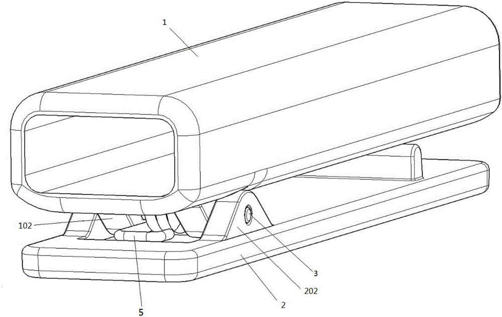
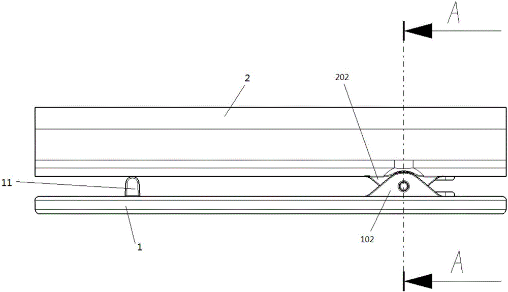
[0032] see Figure 1 to Figure 12 , the electronic product clip includes a first part 1 and a second part 2, the first part 1 includes a first splint 101, the second part 2 includes a second splint 201; both sides of the first splint 101 are provided with shaft holes The shaft hole seat 102 of the first part, and the shaft hole seat 202 of the second part with a shaft hole are arranged on both sides of the second splint 201; the shaft hole seat 202 of the second part is arranged outside the shaft hole seat 102 of the first part;

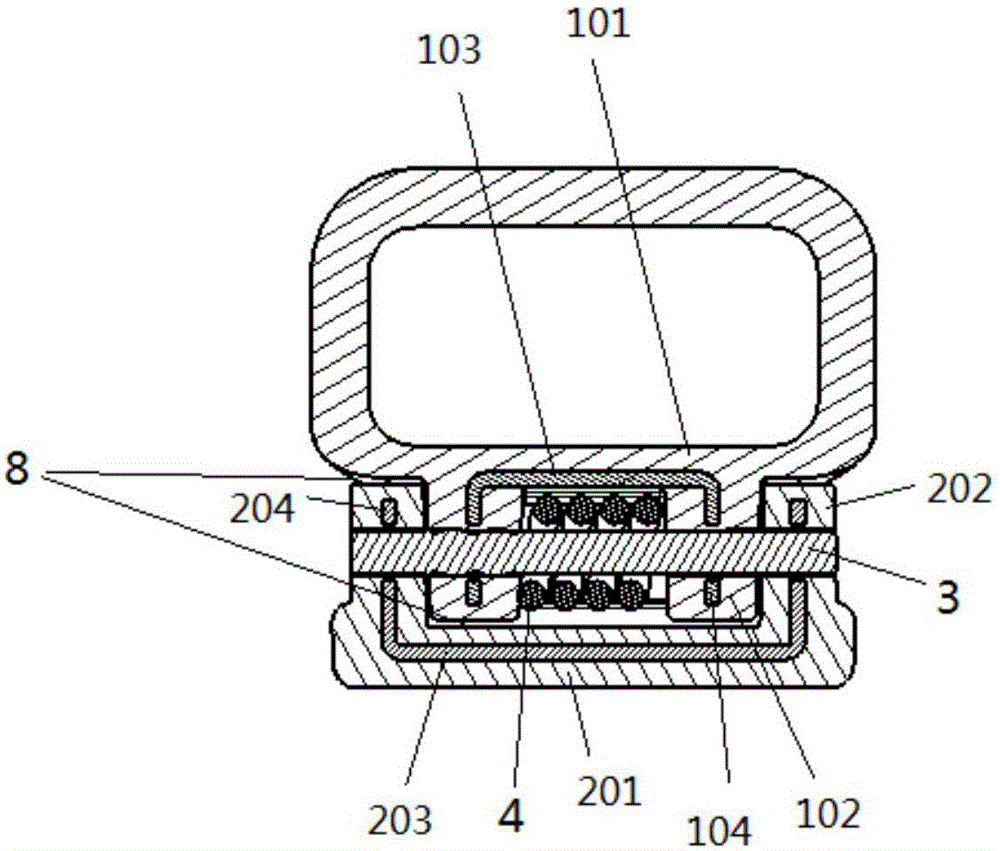
[0033] The inside of the first part 1 is covered with a first insert, and the inside of the second part 2 is covered with a second insert;

[0034] The first insert comprises a first panel 103 and the second insert comprises a second panel 203;

[0035] Both sides of the first panel 103 are provided with a first insert shaft hole seat 104 with a shaft hole, and both sides of the second panel 203 are provided with a second insert shaft hole seat 204 ...

Embodiment 2

[0042] In this embodiment, the description is focused on the materials and structures of the first insert and the second insert of the electronic product clip. For other contents, refer to other embodiments of the present invention.

[0043] In the electronic product clip of this embodiment, both the first insert and the second insert are made of metal.

[0044] It should be noted that the electronic product clip of the present invention can effectively reduce the influence of metal on the radio frequency performance of electronic products by embedding a metal insert in the shaft hole seat of the plastic material clip, and at the same time make the electronic product The product clip not only has the high strength performance of metal clips, but also has the good appearance performance of plastic clips.

[0045] Preferably, the lengths of the first panel 103 and the second panel 203 account for 20%-30% of the lengths of the first splint 101 and the second splint 201 respective...

Embodiment 3

[0050] This embodiment focuses on the description of a specific realization of the structure required by the manufacturing process of the clip for electronic products. For other content, refer to other embodiments of the present invention.

[0051] see Figure 6 , Figure 7 , Figure 10 and Figure 11 , In the electronic product clip of this embodiment, the first insert and the second insert are respectively provided with a space-avoiding through hole 6 and a space-avoiding groove 7 .

[0052] It should be noted that, in the electronic product clip of the present invention, the first part 1 and the second part 2 made of plastic are respectively coated on the outside of the first insert and the second insert made of metal, and the first part 1 made of plastic 1. The second part 2 can be made by injection molding process respectively, and its air-avoiding through hole 6 can be set as a circular hole or a rectangular hole according to needs and actual conditions, and its numbe...


PUM


Abstract

The invention discloses an electronic product clamp. The electronic product clamp comprises a first component and a second component, wherein the first component is provided with a first component shaft hole base, and the second component is provided with a second component shaft hole base; the first component shaft hole base is arranged at the outer side of the first component shaft hole base; a first insert and a second insert are arranged inside the first component and the second component in a covered mode correspondingly; the first insert comprises a first insert plate, and the second insert comprises a second insert plate; a first insert shaft hole base provided with a shaft hole is arranged on the two sides of the first insert plate, and a second insert shaft hole base provided with a shaft hole is arranged on the two sides of the second insert plate; a rotary shaft stretches into the shaft holes; and the rotary shaft is sleeved with a spring, and elastic supporting rods which make contact with the inner wall of a first clamping plate and the inner wall of a second clamping plate are arranged at the two ends of the spring in an extending mode correspondingly. By adoption of the technical scheme, the problems that an existing electronic product clamp is insufficient in strength, large in deformation, large in size, high in cost and the like can be solved; and the electronic product clamp is high in strength, small in size, low in weight and low in cost.

Description

technical field [0001] The invention relates to the technical field of electronic product accessories, in particular to an electronic product clip. Background technique [0002] With the improvement of people's requirements for the portability of electronic products, electronic products such as earphones, remote control, mp3 players, etc. often need to be fixed on the user's clothing through clips, but because the clips made of pure metal will affect the radio frequency performance, and pure metal The manufacturing cost of clips made of materials is high, so most electronic products cannot use pure metal clips, so they all use plastic clips, and plastic clips generally have problems such as insufficient strength, large deformation, and easy breakage at the shaft . [0003] In order to solve problems such as insufficient strength, large deformation, and easy breakage at the rotating shaft, existing clips for electronic products often use methods such as increasing the size o...

Claims


Application Information

Patent Timeline
Patent Type & Authority Applications(China)
IPC IPC(8): F16B2/10
CPCF16B2/10
Inventor 兰向东
Owner 青岛随云电子科技有限公司
Why Eureka
Try Eureka