Camshaft having a closing cover

A technology of camshaft and closing cover, applied in the direction of cams, components with teeth, engine components, etc., can solve the problems of inability to supply oil, change of oil pressure state, blockage of supply holes, etc.

Active Publication Date: 2017-02-15
THYSSENKRUPP PRESTA TECCENTER AG
View PDF6 Cites 2 Cited by
  • Summary
  • Abstract
  • Description
  • Claims
  • Application Information

AI Technical Summary

Problems solved by technology

This sliding firstly causes a change in the oil pressure state in the camshaft and secondly blocks the supply hole (Versorgungsbohrungen) or cuts off the supply hole so that it cannot supply oil

Method used


Image

  • Camshaft having a closing cover
  • Camshaft having a closing cover
  • Camshaft having a closing cover

Examples


Embodiment Construction

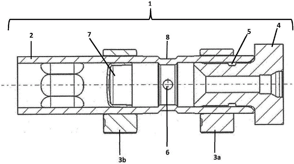
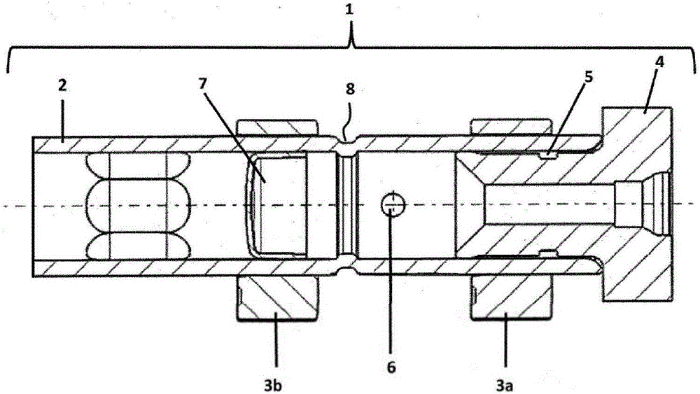
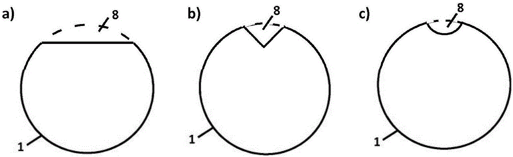
[0034] figure 1 A camshaft 1 is shown comprising a hollow shaft 2 fitted with cams 3a and 3b and closed by an end piece 4 provided with an annular seal 5 . The camshaft 1 is provided with supply openings 6 via which oil is supplied to adjacent bearings and devices. In order to prevent oil from penetrating into undesired areas, a closure cover 7 is positioned in the camshaft. In the example shown, the closure cover 7 has been pressed under the cam 3 b and is thus clamped in the hollow shaft 2 . The closure cover 7 is axially spaced from the cam 3a. In order that the closure cap 7 does not slide during operation and thus does not block the supply opening 6 , a recess 8 in the form of an inwardly rolled part is located in the hollow shaft 2 which prevents the closure cap 7 from sliding. In this example, the recess 8 in the form of an inwardly rolled portion is rotationally symmetrical and is located at the same axial position as the feed hole 6 . The cross-sectional area of ​...


PUM


Abstract

The invention relates to a hollow cylindrical camshaft (1), which is equipped with a closing cover (7) and supply openings (6), wherein sliding of the closing cover (7) is prevented by means of one or more recesses (8) introduced into the camshaft (1). The recesses (8) are rolled-in points, indentations, notches, plastic deformation introduced from outside by means of a punch, or introduced retaining means (9) that protrude into the interior of the camshaft (1). The one or more recesses (8) are arranged in one or more planes orthogonal to the axial direction of the camshaft (1), wherein the one or more recesses (8) can be arranged rotationally symmetrically or symmetrically or asymmetrically in said one or more planes.

Description

technical field [0001] The invention relates to a camshaft comprising a hollow shaft and a closure cover arranged in the interior of the hollow shaft. Background technique [0002] The camshaft can be provided with radial bores through which oil can be conveyed. A closure cover fitted in the camshaft interior ensures that oil cannot penetrate into undesired areas. If a closure cover is present, it is very important that the closure cover does not slip during operation of the camshaft. This slippage firstly causes a change in the oil pressure state in the camshaft and secondly blocks or cuts off the supply bore so that it cannot supply oil. [0003] Hollow cylindrical camshafts with fitted closure covers are known from DE 100 00 916 A1 and DE 10 2006 036 850 A1. Contents of the invention [0004] The object of the invention is to develop the camshaft as a hollow shaft as flexibly as possible without incurring great technical outlay, so that sliding of the fitted closure ...

Claims


Application Information

Patent Timeline
Patent Type & Authority Applications(China)
IPC IPC(8): F01L1/047
CPCF01L1/047F01L2001/0475F16H53/025
Inventor 莫妮卡·贝克迈克尔·博尔德赖纳·阿利马里奥·伊尔格罗思
Owner THYSSENKRUPP PRESTA TECCENTER AG
Why Eureka
Try Eureka